


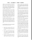

‘TOTAL
PERFORMANCE
IS
WHAT
COUNTS"
CROWN test and check-out procedures reflect our basic design
philosophy; we believe that reliability can be engineered into a
product. As such, our check-out is designed to expose and
correct a problem, before it happens. This testing begins when
the unit is still a pile of parts; grading and selection of
components is standard. The final test-inspection is the culmina-
tion of this vigorous program, but our concern doesn’t stop here.
Our products are backed by an extensive field service program,
and protected by a comprehensive warranty.
A word about our testing procedure is in order. All
our specifi-
cations are referenced to an AC input of 120 VAC. The high
current demand with high power tends to cause the line voltage
to sag, or the sinusoidal waveform to distort. With a distorted
waveform (or lower line voltage) the peak voltage is lowered.
Since it is the peaks that charge the filter capacitors in the
amplifier power supply, and thus determine the maximum power
output, a line voltage problem reduces the maximum power
output. CROWN uses a peak equivalent AC voltmeter which
measures the peaks of any waveform and converts this to an
equivalent rms reading for a sinusoidal waveform. This way we
can vary or regulate the line voltage, no matter how distorted
the waveform, to an equivalent of a 120 VAC sinewave. We are
then measuring a true maximum output power.
With regard to the precision load which we use for our testing,
we realize that a resistive load is quite different than a reactive
speaker. However, using readily available parts, a precision
resistive load is the easiest to duplicate, with respect to
obtaining consistent results. We specify that the load must be
resistive, having less than 10% reactive component at any
frequency up to five times the highest test frequency. The
resistance value should be maintained within
1%,
at all power
levels.
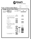
The following discussion examines each of the test procedures
listed on the facing page. This is an attempt to help you under-
stand, in layman’s terms, what the tests mean.
Quiescent Offset
-
This simply
assures
that your
amplifier’s output is balanced with reference to its input.
Thus the amplifier will not “bias” the program with a
dc component. To meet specifications, offset must be less
than 10 mv.
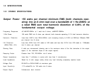
1KHz
-
This test measures the power across an 8 ohm
load at
a frequency of 1 KHz with both channels operating.
This is a determination of how much power an amplifier
can produce before a specified total harmonic distortion
is reached. For the
DC-300A,
the power is 180 watts
at less than
.1%
THD.
4 Ohm Test
-
This is a critical examination of the DC-300’s
performance at impedances below that for which it is
rated. We check the wave form for level (it must reach a
specified voltage before clipping) purity, and stability.
4.
5.
6.
7.
8.
9.
10.
11.
Protection Test
-
This is a test with a 2 ohm load which
determines the threshold at which the protection circuitry
will be activated. Sharp clipping should occur with no
evidence of instability. The positive and negative limiters
operated independently and therefore may not be activated
simultaneously.
Reliability Test
-
This test puts the output stages through
an extremely vigorous
thermal
cycling. The test is a very
low frequency input signal driving the output to full
power across a short circuit for a predetermined period of
time.
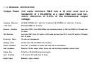
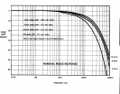
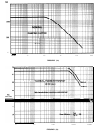
20KHz
-
This tests the amplifier at its rated power level.
We specify that at any frequency between 1Hz and
2OKHz the DC-300A will produce 155 watts minimum
rms (both channels operating) into an 8 ohm load, at a
sum total harmonic distortion of .05% or less. We choose
20KHz
as the test frequency because high frequencies
produce more heat than lower frequencies. Thus, if the
amplifier can safely pass the
20KHz
test, it will operate
safely at lower frequencies.
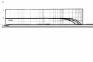
10 KHz Square Wave
-
This test critically examines the
amplifier’s frequency response and rise time. (How fast
the amplifier can follow rapid signal changes.) The output
square wave (with an 8 ohm load) should be clean and
sharp, with no ringing or overshoot.
Mono Operation
-
This is a check for proper operation of
the stereo mono switch. A signal is applied to channel 1
input only and the mono output is observed between the
two red output terminals of the amplifier.
IM
Distortion Test
-
At CROWN we feel that IM
distortion testing yields a truer picture of amplifier
performance than harmonic distortion testing. While a
large amount of documentation supports this opinion,
some of the reasons are apparent, even in layman’s terms.
For example, a sinusoidal waveform (used in HD testing)
bears little resemblance to the complex waveforms
associated with actual program materials. IMD testing
uses such a complex waveform. Also, harmonic distortion
is not always aurally offensive. The human ear may
interpret such distortion as pleasing, but usually finds IM
distortion rather obnoxious. In order to support this
design philosophy, we designed and built our own IM
analyzer with residual noise and distortion low enough to
test our amplifiers.
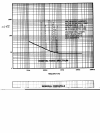
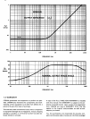
Hum and Noise
-
This test, in plain English, tells you how
small a signal can be amplified without it becoming “lost
in the mud”. The test is limited to the audio band width
of
20Hz-20KHz,
with a bandpass filter. Our specification
for the DC-300A is: hum and noise from
20Hz
-
20KHz
will be at least
110db
below the full power output of 155
watts. This means that with a 155 watt output the noise
will be only
.00155
micro watts. (That’s 1.55 billionths
of a watt
)
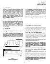
Quiescent AC power Input at 120 VAC
-
This test
confirms that your amplifier is not drawing excessive
power while “idling”. If an amplifier exhibits a tendency
toward instability, or oscillation, it may draw power with
no signal input. The DC-300A will draw 40 watts or less
at idle.