


3.1 CONTROLS AND ADJUSTMENTS
Section 3
OPERATING INSTRUCTIONS
OPERA TING CONTROLS
The DC-300A contains all the facilities essential for a
high performance amplifier.
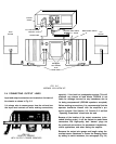
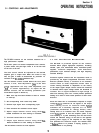
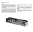
On the front panel are located independent level controls,
a power switch, and pilot light. There is an AC line fuse
on the rear of the unit.
The level control should be adjusted for the desired
amplifier gain or output level. When the control is fully
CW, the gain is 26db as determined by precision 1%
resistors in the
DC-300A’s
feedback loop.
The DC balance controls located behind the front panel
seldom, if ever, need adjustment.
Only
in the most
critical applications will they need adjustment (not
“hi_fi”
or similar applications). To adjust the DC
balance controls, use the following procedures (see
Circuit Board layout in Section 4):
1.
2.
3.
4.
5.
6.
7.
Make sure amp has been allowed at least 15 minutes
of warm-up.
Set corresponding level control fully CCW.
Remove input signal from corresponding input.
Place sensitive DC voltmeter across output.
Adjust output balance control using small
flat-
bladed screwdriver for zero reading on voltmeter.
Turn level control CW to 12 o’clock.
Adjust input balance control using small
flat-
bladed screwdriver for zero reading on voltmeter.
The DC balance controls are now adjusted.
3.2 THE PROTECTION MECHANISMS
The DC-300A is protected against all the common
hazards which plague highpower amplifiers, including
shorted, open, and mismatched loads; overloaded power
supplies; excessive temperature;
chain destruction
phenomena; input overload damage; and high frequency
overload blowups.
Protection against shorted and low impedance loads is
provided by the Signal Programmed Automatic Current
Executor (SPACE control). It functions as an automatic
current limiter at audio frequencies whose value of
current limiting threshold is dependent on the history
of the output signal. Output current causes the threshold
to decrease while output voltage causes the threshold to
increase. The no signal threshold is high enough to
allow tone bursting, (even into 4 ohms) without premature
limiting as is found in some recent products of other manu-
facturers
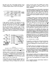
Since the limiter has no instantaneous response to output
voltage, flyback transients do not appear in the output
when limiting occurs on inductive loads. Flyback
transients are a necessary response of a VI limiter
(sometimes misnomered an “Energy Limiter”) when
limiting drive to an inductive load. The actual response
of the flyback pulse is that the amplifier yields to the
load resulting in a pulse emanating from the load which
returns the inductive energy of the load to the opposite
polarity power supply of the amplifier as that supply
that produeed the excessive output. The audible effect
of flyback pulses is to produce a rasping, popping sort
of sound which is not pleasing.
19