


15
40
RL
LOAD
30
RESISTANCE
(ohms)
20
15
10
9
8
7
6
5
4
Rl
R,
DAMPING
7.
.04
8000
5000
s-.06
R,
-
SOURCE
~MOOO
ft.1
--ANNEALED
--
.l
RESISTANCE
1000
T
COPPER
2-COND.
500.-
WIRE
CABLE --
IAWGI
50.---t24
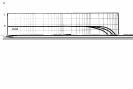
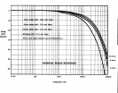
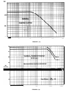
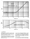
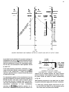
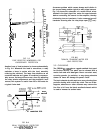
FIG. 2-4
SOURCE RESISTANCE AND DAMPING FACTOR VS. LENGTH AND SIZE OF OUTPUT LEADS
is provided for wire selection. For dynamic moving-coil
loudspeakers the value of
RL
should preferably be that
measured by an ohmmeter across the voice coil, rather
than the manufacturer’s rating. For electrostatic speak-
ers and such, the manufacturer’s rated impedance should
be used for R.
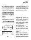
If the load (matching transformer, inductance, or
full-
range electrostatic speaker system) appears as a
short-
circuit at low frequencies, a large non-polarized
capacitor (paralleled with a resistor) should be placed
in series with the load.
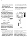
For electrostatic speakers (if the manufacturer has not
provided a capacitor) an external non-polar capacitor of
590-708 mfd and 4 ohm power resistor should be placed
in series with the plus (+) speaker lead. This will pre-
vent large low-frequency currents from damaging the
electrostatic transformer
or from
unnecessarily
activating the
DC-3OOA’s
protective systems. An ef-
fective test to determine if such parts are needed is to
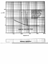
F/G. 2-5
-
SCHEMA TIC FOR FULL RANGE
ELECTROSTATIC SPEAKER CONNECTIONS
measure the DC resistance between the output terminals
with an ohmmeter. If the resistance is less than 3 ohms,
the parts should be added as shown schematically
in Fig. 2-5.
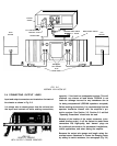
When selecting connectors for the output lines, the follow-
ing general precautions apply (with all power connectors):
1. A male plug, carrying signal, must not be on the
far end of the line where it can be exposed, giving
rise to both shock and short-circuit hazards.