


APPLICATION NOTE NO. 1
V-l LIMITS OF A LOAD
Evaluating the V-l (volt-ampere) needs of a load: Many
loads exhibit large
reactances
(or energy storage),
which limits a power amplifier’s ability to deliver a
maximum power. If a load stores energy, which in turn
flows back into the amplifier, it is clear that the max-
imum power efficiency of the system is not being
achieved. Power that flows back into a linear amplifier
must necessarily be dissipated in the form of heat. A
pure reactance is not capable of dissipating any power;
therefore to drive such a load would only cause power
amplifier heating.
In practice all loads exhibit some energy dissipation
-
however large their energy storage characteristics may
be. The ideal coupling to any load is one that optimizes
the desired dissipation component while minimizing the
reactive or stored-energy component that is seen by
the amplifier’s output terminals.
cl
scope
Section 5
APPLICATION NOTES
In applications where the input is sinusoidal and of small
proportional frequency deviation, a relatively stable load
may be resonantly tuned to present a real value of im-
pedance to the amplifier.
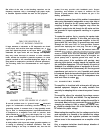
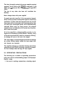
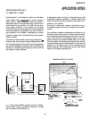
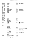
Any load, no matter how complex its behavior, has a
V-l operating range which may be mapped by the follow-
ing test.
The maximum voltage and amperage excursions in all
directions about zero (center of scope screen) define
the volt-ampere operating range of the load. If a load is
known to be linear over its operating range it is not nec-
essary to supply the maximum desired power to the load.
The test may be conducted at low signal levels and the
current-sensing resistor (indicated as 0.1 ohm) may be
enlarged to a convenient value for the oscilloscope’s de-
flection sensitivity. The resulting plot may be then linearly
scaled to the desired operating level.
LOAD
under
ted
Note: Scope and amplifier grounds are not common.
Vertical input reads (-) amperes vertically. If scope
has an inverter, invert to read (+) A.
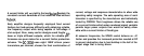
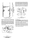
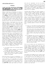
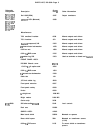
AMPLIFIER LIMITS OF VI OUTPUT
V
out
-
-
MID-FREDVENCY
BURST
LIMIT
.
.
.
AC
LINE
F”SE
BLOWS
[DC
SINGLE
CHAN.l
SLOWS
X
SHORT CIRCUIT CONTINUOUS LIMIT
AT
10A
DC IF BOTH AREA OVER
WHICH
LIMITER (AC)
CHANNELS ARE DRIVEN
“ARIES (SIGNAL DEPENDENT)
EDUALLY
-MAX AC LIMIT
It‘,
V OUT
ISINEI
AT
MAX.)
-
MAX. CONT. AC POWER
,ZA
=
2.75*)
----
HlGH
FREDVENCY
LIMIT
25