


25
S
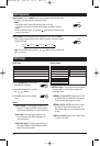
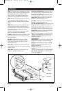
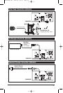
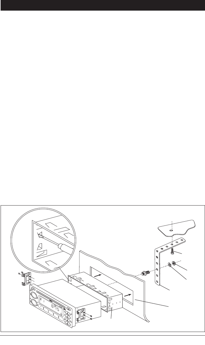
tep 1:
The radio chassis is designed to be “Sleeve
Mounted” through a opening in the dashboard panel.
The required opening size is 182mm (7-3/16") x
84mm (3-5/16"). Cut or engage an opening in the
dashboard to accommodate the mounting sleeve.
Step 2: Insert the mounting sleeve into the hole
in the dashboard. Bend the metal tabs on the
sleeve to secure the mounting sleeve to the dash-
board.
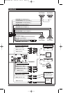
Step 3: Bring all wiring for the connection of the
unit (including the antenna) through the center of
the mounting sleeve. Connect the wiring as follows:
Yellow Wire (w/Fuse): Connect this wire to a
constant +12 volt power source (a power source
that is not controlled by the ignition key).
Red Wire: Connect this wire to a switched +12 volt
power source (a power source turned on and off
by the ignition key).
Blue Wire: Connect this wire to the (+) power
antenna activation circuit. If no power antenna
exists, tape-off the end of this wire to prevent
shorting out the unit.
Black Wire: Connect this wire to the frame of the
vehicle (ground). This wire is the chassis grounding
wire for the unit.
White Wire: Connect this wire to the Left Front
Speaker (+) positive terminal or wire.
White Wire with Black Stripe: Connect this wire to
the Left Front Speaker (-) negative terminal or wire.
Gre
en Wire with Black Stripe: Connect this wire to
the Left Rear Speaker (-) negative terminal or wire.
Green Wire: Connect this wire to the Left Rear
Speaker (+) positive terminal or wire.
Gray Wire: Connect this wire to the Right Front
Speaker (+) positive terminal or wire.
Gra
y Wire with Black Stripe: Connect this wire to the
Right Front Speaker (-) negative terminal or wire.
Purple
Wire with Black Stripe: Connect this wire to
the Right Rear Speaker (-) negative terminal or wire.
Purple Wire: Connect this wire to the Right Rear
Speaker (+) positive terminal or wire.
Note: This unit is designed to connect to (4) four
speakers. If the installation only requires (2) two
speakers, use the White and Gray wire sets to
connect the speakers.
WARNING! Any wires left unconnected must
be taped-off or capped off to prevent shorting.
DO NOT connect speaker ground wires together.
DO NOT connect speaker ground wires to the
chassis of the vehicle.
DO NOT connect front and rear speaker wires
together.
FAILURE TO FOLLOW ANY OF THESE WARNINGS
WILL RESULT IN DAMAGE TO THIS UNIT AND
VOIDS THE WARRANTY.
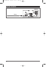
Installation
2
3
4
5
MEM
ORY
REPE
AT
PRO
G
RAM
S
H
U
FF
LE
SCA
N
BAND
W-B
AN
DIS
P
MOD
AS
/
PS
LOU
D
MUT
EQ
TUNE/TRACK
VOLUME
POWER
EJECT
ELAPSE
D
I
M
/ II
SCAN/SHIFT
PUSH SEL/
MENU
LOC
Nut
Washer
Sheet
Metal
Screw
Metal Strap
Dashboard
Mounting Sleeve
M9900DVDS-UM 4/26/06 14:17 Page 25