


551Razur
7
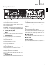
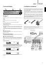
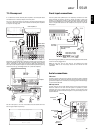
Rear panel connections
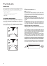
& FM/AM antennas
All tuner antenna connections are made here. Refer to the ‘Antenna
Connections’ section of this manual for more information.
Emitter In
Allows modulated IR commands from multi-room systems or IR repeater
systems to be received by the 551R.
Service/Normal
For dealer use only - Switches the 551R between normal (default) mode and
two Service modes. Do not change the mode to service or make RS232
connections to it in service mode as damage may result!
Composite and S-Video inputs
These may be freely assigned to any source, see later section.
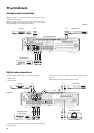
RS232C
Used for control of the 551R in Custom Install situations. A full protocol is
available for the 551R on our website.
Analogue Audio inputs
For use with the line level outputs of CD players, BD/DVD players etc.
Tape/MD/CDR In / Out
For use with suitable recording devices. The output allows recording of the
currently selected analogue source.
Digital Inputs
S/P DIF or Toslink digital inputs for each source.
You can choose to use a different type for each source but do not connect
both at the same time for the same source.
Digital Outputs
S/P DIF and Toslink digital outputs for recording . The outputs allow recording
of the currently selected digital source.
These are concurrent and both can be connected at the same time.
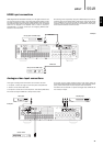
7.1 Preamp Out
Connect to the 5.1/7.1 channel input terminals of another amplifier system,
separate power amps, subwoofer or active loudspeakers.
7.1 Direct In
Connect to the output terminals of a DVD-A, SACD player or other 5.1/7.1
analogue source.
Heat tunnel vent grille
Allows cooling of internal circuitry via the 551R’s proprietary X-TRACT heat
tunnel. DO NOT OBSTRUCT!
& HDMI
Inputs and output to a suitable TV/Monitor. The HDMI inputs can be assigned
in the OSD. By Default the HDMI inputs are assigned to BD/DVD, Video 1 and
Video 2, with the 4th input unassigned.
These inputs can be freely assigned, see later section on assigning video
inputs.
All video inputs whether analogue or HDMI are transcoded and output via the
HDMI output.
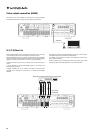
Component Video inputs
By default the component inputs are unassigned, these inputs can be freely
assigned, see later section on assigning video inputs.
Note: The preferred connection method for video inputs is always Composite
Video, then S-Video, then Component Video, then HDMI in ascending order
of quality (HDMI being the highest quality). HDMI and Component Video
sources often also support Progressive Scan which gives better picture
quality if supported by both your BD/DVD player and TV.
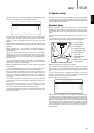
. Speaker terminals
Connect to loudspeakers with an impedance of between 4-8 ohms. 7.1, 5.1
or less connections can be made.
Power On/Off
Switches the unit on and off.
Mains power lead
Once you have completed all connections, plug the AC power lead into an
appropriate mains socket. The AV receiver is now ready for use.
1
1 2
15
14
16
17
18
19
3
4
5
6
7
8
9
10
11
12
13
5
4
3
6
7
9 10
8 12
14 15
17
16
18
19
11
13
ENGLISH
2