


8
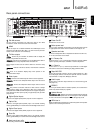
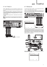
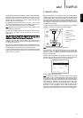
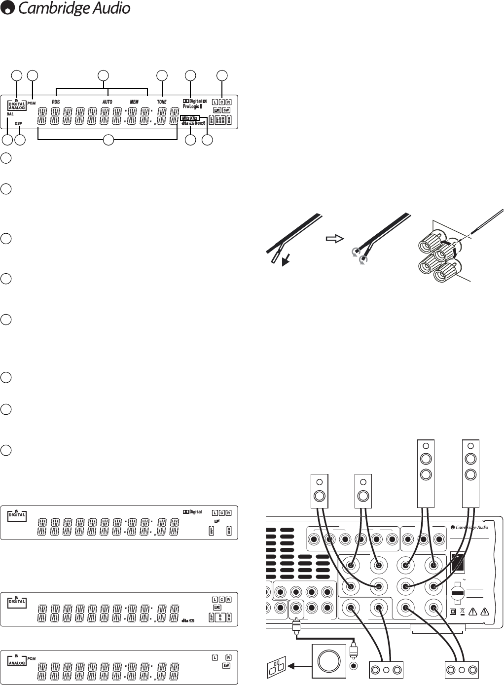
Front panel display
Digital/Analog indicators
Indicates the current source input type - digital or analog.
Decoding mode indicators
Shows the current decoding mode, Dolby Digital, Dolby Digital EX etc. In
conjunction with the Output Channel indicators these give full details of
the current processing mode.
Tuner mode indicators
Shows Memory/Store active, Stereo mode active, AutoScan active and
RDS On.
Tone control indicator
Lights when Bass and Treble controls are active i.e. have been set to
anything other than 0dB (flat) position.
Output channel indicators
Shows the currently active channels depending on decoding mode and
source material. Icons lit indicate active channels in the source material.
Icons with a box around them indicate actual channels being output
separately.
Frequency type
Indicates the tuned frequency in AM or FM Tuner mode.
Main information display
Shows the current source selected, also the surround mode and station
name/frequency when in tuner mode etc.
Balance indicator
Lights when the Front Left and Right speaker outputs have been set to
different levels in the OSD, i.e. a balance adjustment has been made.
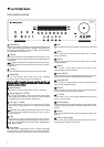
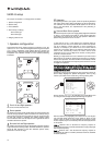
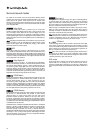
Display examples
- Indicates a 5.1 Dolby Digital source being played back as 5.0 (Sub off).
LFE indicates a low frequency effects channel is present in the source
material. When this icon isn’t boxed it indicates the LFE channel is not
being reproduced separately.
- Indicates a 6.1 playback of DTS ES material.
- Indicates a 2.1 output created in the digital domain from analog input
material.
1
2
3
4
5
6
7
8
41 3
7
2
8 2 2
2 5
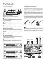
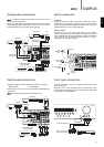
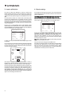
To avoid damaging the speakers with a sudden high-level signal, be sure
to switch the power off before connecting the speakers. Check the
impedance of your speakers. Speakers with an impedance of between
4 and 8 ohms (each) are recommended.
The coloured speaker terminals are positive (+) and the black speaker
terminals are negative (-). Make sure correct polarity is maintained at
each speaker connector or the sound can become weak and “phasey”
with little bass.
Prepare the speaker cords for connection by stripping off approximately
10mm (3/8”) or less (no more than 10mm, as this could cause a short-
circuit) of the outer insulation. Twist the wire tightly together so there are
no loose ends. Unscrew the speaker terminal knob, insert the speaker
cable, tighten the knob and secure the cable.
Note:
All connections are made via loudspeaker cable, except if using an
active subwoofer which would be connected via a standard RCA phono
cable. Banana Plugs (4mm standard) connected to the speaker cable
are recommended for direct insertion into the speaker terminals.
Please refer to the ‘Speaker configuration’ section of this manual for
more information on 5.1 and 6.1 speaker setups.
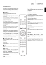
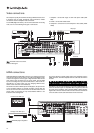
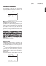
Loudspeaker connections
Sur
Left
Sur
Right
Sur
Back
Left
Right
Centre
SB
SB
WSW
C
SR R
SL L
Power AC
Cr/Pr Cb/Pb Y Cr/Pr Cb/Pb Y
Cr/Pr Cb/Pb Y
Component Video In
In 1 In 2
TV/Mon Out
Designed in London, England
www.cambridge-audio.com
Caution
Risk of electric shock.
Do not open.
Avis
Risque de choc electrique.
Ne pas ouvrir.
Achtung
Vorm öffnen des gerätes.
Netzstecker ziehen.
azur 540R v3.0 AV Receiver
Max Power Consumption: 615W
Power Rating: 230V AC ~ 50Hz
6.1 5.16.1 Preamp Out
Power
On
Off
entilation. Ventilation nicht verschließen.
Component Video
(Assignable)
Speaker Impedance 4-8 Ohms
Front right
speaker
Front left
speaker
Surround
left speaker
Surround
right speaker
Front centre
speaker
Surround back
speaker
Powered
subwoofer
PPhhoonnoo//RRCCAA
ccaabbllee
6