


14 of 36
4.0 Hardware Installation
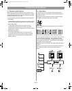
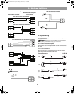
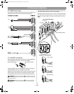
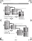
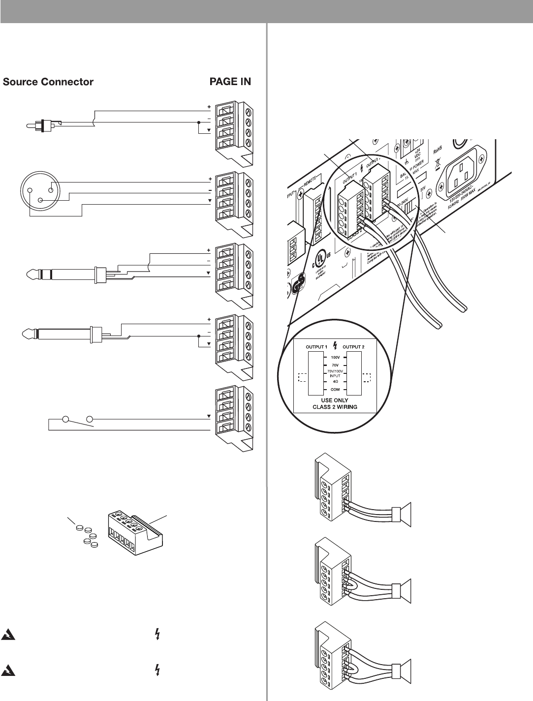
4.7.3 PAGE source input
A microphone or another paging source can be connected to the
PAGE INPUT jack using one of the following cable types.
Normally
Open Switch
(latching)
XLR
3
1
2
3
Phone
Plug
(Balanced)
T R S
T
R
S
RCA
T
S
12
Phone
Plug
(Unbalanced)
T
S
T
S
TS
PTT
PTT
PTT
PTT
PTT
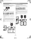
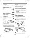
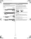
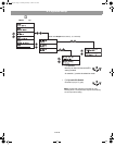
4.7.4 OUTPUT connections
Use the supplied 5-terminal connectors for wiring loudspeakers
to the output jacks on the rear of the mixer/amplifier.
5-terminal connector
Screw terminal caps
Insert the speaker wire into the proper terminals for the type of
voltage needed, as shown in the figure on the right.
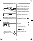
Tighten the screws to hold the wires in place, and insert the screw
terminal caps to cover each screw. These caps prevent making
contact with the screws, which could cause an electrical shock.
WARNING: Terminals marked with are hazardous live. The
external wiring connected to these terminals should be installed by
an instructed person.
WARNING: Terminals marked with should be connected
to the loudspeakers such that the metal parts of its terminal are
inaccessible.
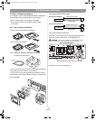
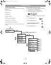
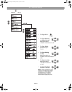
Follow the diagram below to insert the 5-terminal connector into
the output jacks on the back of the mixer/amplifier.
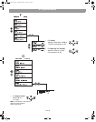
Notice the proper wiring for 4 ohm, 70 volt or 100 volt uses. Both
70V and 100V wiring require the use of a jumper cable, as shown.
Note: Use 12 AWG (4 mm2) to 20 AWG (0.5 mm2) gauge wire for the
jumper.
Rear connection panel
Input voltage switch
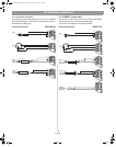
4 Ohm wiring
70 Volt wiring
100 Volt wiring
OUTPUT 1
OUTPUT 2
OUTPUT 1 and OUTPUT 2
4.0 Install and Wiring.fm Page 14 Monday, February 12, 2007 8:52 AM