


10 of 36
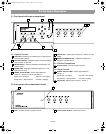
4.0 Hardware Installation
4.1 Introduction
This section provides instructions for installing and wiring the
Bose FreeSpace
®
DXA 2120 Digital Mixer/Amplifier.
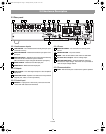
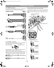
4.2 Included accessories
• 3-terminal input connectors (4) – For wiring
equipment to the MIC/LINE INPUT Euroblock
jacks.
• 4-terminal input connectors (2) – For wiring
equipment to the single PAGE INPUT and
single DIRECT INPUT jacks.
• 6-terminal input connector (1) – For wiring
to the REMOTE jack.
• 5-terminal output connectors (2) with
screw caps – For wiring
speakers to
OUTPUT 1 and OUTPUT 2.
• 3-terminal output connector (1) – For wiring to
the AUX OUTPUT jack.
• Rubber feet (4) – For installing the chassis on a
level surface.
• Rack ears
with
Rack ears
(6) #8-32 x 1/2 in
mounting
hardware (2) –
For installing the
mixer/amplifier
chassis (2U) in a
rack.
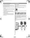
4.3 Placement guidelines
For placement of the mixer/amplifier chassis, keep the following
in mind:
• Make sure that air can circulate freely behind, beside, and
above the chassis for adequate ventilation. There are intake
vents on the sides and an exhaust vent on the back of the unit.
Do not cover or block the vents.
• Make sure the chassis is protected from heat and kept away
from direct heat sources, such as heating vents and radiators.
CAUTION: Do not allow the chassis to exceed the maximum
operating temperature of 50° C (122° F). Be aware of conditions in
an enclosed rack that may increase the temperature above room-
ambient conditions.
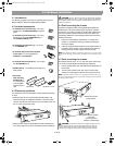
4.4 Shelf mounting the chassis
The Bose
®
FreeSpace
®
DXA 2120 Digital Mixer/Amplifier has
rubber feet for use when positioning the chassis on a shelf or
counter top. They help to protect the surface that supports the
unit and to prevent chassis movement. Be sure to follow the
“Placement guidelines” previously described when choosing a
location for the unit.
1. Place the mixer/amplifier upside-down on a solid, level
surface on a protective covering to avoid scratching the
top of the chassis.
2. Insert the supplied rubber feet to the four existing holes on
the bottom of the chassis. Use a screwdriver to push the
locking pins fully into the chassis, securing the feet.
Note: The rubber feet may be removed by inserting a screwdriver into
the screw and turning counterclockwise until the screw backs out of the
hole.
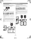
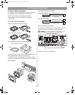
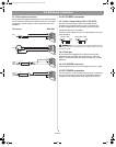
4.5 Rack-mounting the chassis
The chassis requires two 1.75" (4.4 cm) rack-space units with a
16" (40.6 cm) inside depth (including the rear supports).
1. Use the supplied rack ears and hardware for attachment to
the chassis.
2. To secure the chassis to the rack, use four screws with
washers (not provided) to prevent marring the front panel.
Note: Neoprene rubber washers are a good choice because they grip
the screw head and prevent the screws from backing out from vibration
or during transportation.
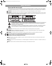
Attaching rack ears
to the chassis
Mounting the chassis
in the rack
(rack screws and
washers not provided)
CAUTION: To transport the rack-mounted chassis, be sure
the rear of the chassis is supported mechanically in the rack.
Install a shelf under the unit or use brackets for rear support.
Lack of proper support may result in damage to the chassis.
4.0 Install and Wiring.fm Page 10 Monday, February 12, 2007 8:52 AM