


English
CONNECTIONS
& CONTROLS
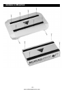
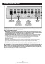
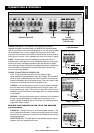
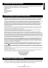
SPEAKER OUTPUTS - The amplifier is connected to appropriate
impedance speakers via these leads. It is IMPERATIVE that these leads
NOT be connected or touch the vehicle chassis in any way or the amplifier
will be damaged. The (+) and (-) leads of the amp are in no way inter-
connected to one another. Also, NONE of the leads can touch each other,
touch ground, or touch +12V or damage may occur to the amp or vehicle.
FUSES - These fuses are only for catastrophic situations should the
amplifier begin to self-destruct or incur installation situations where gross
amounts of current are being required from the amp beyond its design
limits. Although another fuse should be installed inline with the high power
line at the battery, these amplifier mounted fuses MUST remain in the
circuit to protect the amplifier.
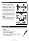
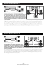
POWER CONNECTIONS & TRIGGER LINE
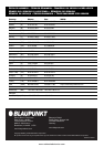
+12v - A high current line run direct from the batter is highly
recommended to insure adequate current and voltage. This line MUST
be run through a dedicated fuse of some kind and this fuse should be
located immediately next to the power source. This in-line fuse is used
to protect the vehicle should a short to chassis occur.
TRIGGER - This line tells the amp to turn on and is remotely switched
from the radio which normally provides an amp “trigger” output. This
line is required to go “high” (+12V) to turn on the amp. If this line is not
available, use the power antenna line trigger which is normally available
in most radios.
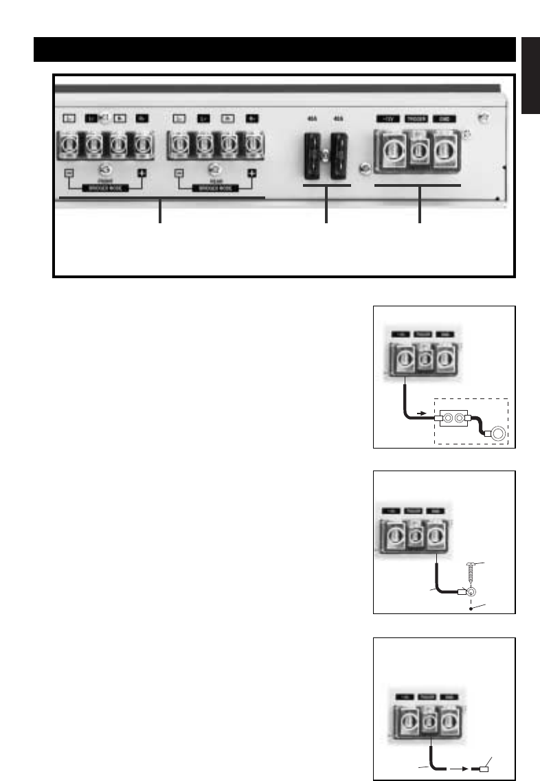
GROUND - This is the high current ground connection to the chassis of
the car. It should be fastened to a clean ground connection in the
vehicle, capable of handling high current loads. This wire should be no
longer than 3 feet (1 meter).
BLUE DOT LIGHT INDICATOR ON THE TOP OF THE AMPLIFIER
(not shown above)
POWER ON - This light will turn on when the amplifier receives a +12V
turn-on signal from the radio. If the amp is properly wired, but the light
does not turn on, there may be a short circuit condition that the amp is
protecting itself from.
PROTECTION LED - This light flashes if the amplifier senses a severe
problem, such as a speaker short circuit.
SPEAKER OUTPUTS FUSES
POWER
CONNECTIONS &
TRIGGER LINE
10 Gage
Wire
To Battery
Terminal
NOT SUPPLIED
Fuse or
Circuit Breaker
Battery
Terminal
Adapter
10 Gage
Wire
Ring
Connector
Sheet
Metal
Screw
Drill 1/8” hole
in chassis
sheet metal
18-20 Gage
Wire
To Receiver
Power
Antenna Lead
Butt
Connector
(not supplied)
+12V Terminal
Trigger Terminal
Ground Terminal
Connect directly to the vehicle battery (+)
terminal with 10 gage wire (minimum)
Connect to a good chassis ground. The
ground connection should be clean,
unpainted metal to provide a good electrical
connection.
Connect the radio power antenna lead from
the receiver to the trigger terminal. This
turns the amplifier on whenever the receiver
is turned on.
– 8 –
www.midwestelectronics.com