


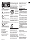
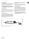

8 SUPER-X PRO CX3400 User Manual
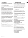
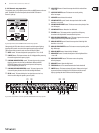
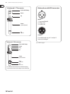
Fig. 2.6:
(1) (5)(4) (6) (9) (12) (15) (16)
(2) (3) (11) (14)(8)
(7) (10) (13)
(30)
(31)
Active control elements on the front panel of the SUPER-X PRO for stereo 3-way operation
(1) and (16) INPUT control. This control adjusts the input gain from
+12 to -12 dB.
(2) LOW CUT button. This button activates the 25 Hz highpass lter protecting
the woofers against low-frequency signals.
(3) LOW/MID XOVER FREQ. control. This control governs the crossover
frequency between the Low and Mid bands. When the XOVER FREQUENCY
button on the rear of the unit is pressed, the frequency range is multiplied
by the factor 10.
(4) MID/HIGH XOVER FREQ. control. This control governs the crossover
frequency between the Mid and High bands.
(5) DELAY control. This control delays the Low signal by as much as 2 ms,
which is useful to align the speaker systems in phase.
(6) LOW OUTPUT control. Controls the output level of the Low band from
+6 to -6 dB.
(7) LOW PHASE INVERT button. This button reverses the polarity
of the Low output.
(8) LOW MUTE button. Mutes the Low band.
(9) MID OUTPUT control. Controls the output level of the Mid band from
+6 to -6 dB.
(10) MID PHASE INVERT button. This button reverses the polarity
of the Mid output.
(11) MID MUTE button. Mutes the Mid band.
(12) HIGH OUTPUT control. Controls the output level of the High band from
+6 to -6 dB.
(13) HIGH PHASE INVERT button. This button reverses the polarity
of the High output.
(14) HIGH MUTE button. Mutes the High band.
(15) CD HORN button. This button provides a special form of frequency
correction in the High band for constant-directivity horns.
(30) THRESHOLD control. This control determines the limiter threshold.
(31) LIMITER button. This button activates all limiters. Whenever the signal
surpasses the limiter threshold, the LIM-LEDs above the Gain control
light up, signaling that the CX3400 cuts back the output level.
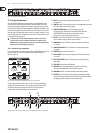
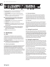
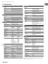
Fig. 2.7:
(3) (4) (8) (9) (10) (11) (12) (13) (14)
Active control elements on the rear panel of the SUPER-X PRO for stereo 3-way operation
(4) and (11) MID OUTPUT connector. Output for the Mid band signal.
(3) and (10) HIGH OUTPUT connector. Output for the High band signal.
(8) MODE button. In stereo 3-way mode, both buttons must be out.
Please observe the labels on the rear panel of the unit.
◊ Always switch off the entire system before you press this button,
as it produces heavy interference noise that could damage your
speakers and/or other equipment.
(9) LOW SUM button. In stereo mode, the two Low paths can be summed
with the LOW SUM button and routed to the Low output of channel 1,
which is particularly useful in systems using additional subwoofers.
(12) LOW (LF SUM) OUTPUT connector. Output for the Low band signal.
(13) XOVER FREQ. button. This button serves to switch over the control range
of the front-panel LOW/MID XOVER FREQ. control from 44 to 930 Hz or
440 Hz to 9.3 kHz.
◊ Always switch off the entire system before you press this button,
as it produces heavy interference noise that could damage your
speakers and/or other equipment.
(14) INPUT connector. Input signal connector.