


6 SUPER-X PRO CX3400 User Manual
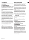
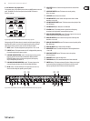
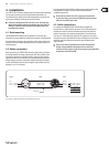
Fig. 2.1: The front panel of the SUPER-X PRO
2.3 Control elements
Since the SUPER-X PRO boasts a variety of features, we highlighted the active
control elements in the following illustrations. On the unit itself, these active
elements are equipped with light-emitting diodes, helping you to keep track of
your settings even under poor lighting conditions. Additionally, all buttons on the
front panel are backlit when activated. Above the control elements there are two
labels in the form of strips which refers to mono 4-way (upper) or stereo 2/3-way
(lower) conguration. The LEDs below these strips show which controls are active
in the respective operating mode.
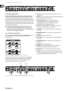
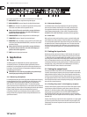
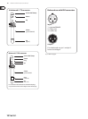
◊ On the rear panel, labels above/below the connectors refer to the
various crossover modes available. Please make sure that the two
MODE switches and corresponding connectors are configured properly;
otherwise, you could damage your speakers.
2.3.1 Stereo 2-way operation
First, activate stereo 2-way mode by means of the two MODE buttons on the rear
panel. The STEREO-LED on the front panel, above the LOW CUT button in
channel 2, lights up.
Fig. 2.2: Proper selection of the two MODE buttons for stereo 2-way operation
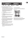
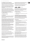
Subsequently, the LEDs above the active controls on the front panel light up,
signaling which controls are active in the operating mode you just selected.
The functions of these controls can be seen from the second strip label.
In stereo mode, both channels perform the same functions.
(1) INPUT control. This control adjusts the input gain from +12 to -12 dB
(see control 16).
(2) LOW CUT button. This button activates the 25 Hz highpass lter protecting
the woofers against low-frequency signals.
(3) LOW/HIGH XOVER FREQ. control. This control governs the
crossover frequency between the Low and High bands. When the
XOVER FREQUENCY button on the rear of the unit is pressed,
the frequency range is multiplied by the factor 10.
(5) DELAY control. This control delays the Low signal by as much as 2 ms,
which is useful to align the speaker systems in phase.
(6) LOW OUTPUT control. Controls the output level of the Low band from
+6 to -6 dB.
(7) LOW PHASE INVERT button. This button reverses the polarity of the
Low output.
(8) LOW MUTE button. Mutes the Low band.
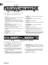
(12) HIGH OUTPUT control. Controls the output level of the High band from
+6 to -6 dB.
(13) HIGH PHASE INVERT button. This button reverses the polarity of the
High output.
(14) HIGH MUTE button. Mutes the High band.
(15) CD HORN button. This button provides a special form of frequency
correction in the High band for constant-directivity horns.
(30) THRESHOLD control. This control determines the limiter threshold.
(31) LIMITER button. This button activates all limiters. Whenever the signal
surpasses the limiter threshold, the LIM-LEDs above the Gain control light
up, signaling that the CX3400 cuts back the output level.
Fig. 2.3:
(7) (13)
(30)
(31)
(15)
(14)
(5) (6)
(8)
(12)(1) (3)
(2)
Active control elements on the front panel of the SUPER-X PRO for stereo 2-way operation