


10 SUPER-X PRO CX3400 User Manual
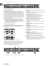
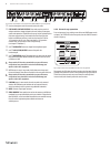
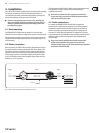
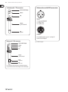
Fig. 2.10:
(3) (4) (8) (11) (12) (13) (14)
Active control elements on the rear panel of the SUPER-X PRO for mono 4-way operation
(3) HIGH OUTPUT connector. Output for the High band signal.
(4) HIGH-MID OUTPUT connector. Output for the High-Mid band signal.
(8) MODE button. In mono 4-way mode, the right button must be pressed.
Please observe the labels on the rear panel of the unit.
◊ Always switch off the entire system before you press this button,
as it produces heavy interference noise that could damage your
speakers and/or other equipment.
(11) LOW-MID OUTPUT connector. Output for the Low-Mid band signal.
(12) LOW OUTPUT connector. Output for the Low band signal.
(13) XOVER FREQ. button. This button serves to switch over the control range
of the front-panel LOW/LOW-MID XOVER FREQ. control from 44 to 930 Hz
or 440 Hz to 9.3 kHz.
◊ Always switch off the entire system before you press this button,
as it produces heavy interference noise that could damage your
speakers and/or other equipment.
(14) INPUT connector. Input signal connector.
3. Application
3.1 Tools
The following tools are indispensable for a perfect system alignment.
You should by all means try to obtain the speaker specications from the
manufacturer, in order to operate the systems in their proper frequency and
level ranges. Use the manufacturer’s documentation to adjust the operating
mode and crossover frequencies.
◊ BEHRINGER does not assume any responsibility for speaker damage
caused by improper handling of the SUPER-X PRO.
3.1.1 Measuring microphone
For making measurements you need a high-grade microphone with a frequency
response that should be as linear as possible over the entire frequency range
(e.g. BEHRINGER measuring microphone ECM8000), or at least between
90 Hz and 15 kHz. Place the microphone about 5 m in front of the speaker
system to be measured, in a height where it is on axis with the drivers of the two
frequency bands you wish to measure. When setting the levels for the individual
frequency bands, delay times and crossover frequencies by means of
a measuring microphone, you should operate only one speaker stack each.
Usually, the measuring microphone needs to be repositioned between two
specic measurements.
3.1.2 Generator/Analyzer
In combination with a measuring microphone and a generator producing
pink noise that is fed into a channel of your P.A. console, an analyzer gives
you a graph that shows how the acoustic energy is distributed among the
various frequency bands (usually 1/3 of an octave). The equalizer/analyzer
BEHRINGER ULTRA-CURVE PRO DSP8024 is the ideal tool for this application.
3.1.3 Your ears
When you listen to the overall sound of your system, you should walk around
in the audience area and try to detect resonance frequencies or cancellations.
The sound should be optimized for the position where most of the audience will
be gathered, however, without neglecting other areas. This often means that
the system must be operated in mono. Whenever you use technical aids such
as analyzers, measuring microphones, etc., you should check the results with
your ears.
3.2 Setting the input levels
Both inputs provide a gain boost/cut of up to 12 dB. Normally, the output level
of the mixing console and the input sensitivity of the power amp are the same,
i.e. 0 dB in the console correspond to 0 dB in the amplier. In this case, the power
amp is fully driven and the SUPER-X PRO should have no inuence on the system
level, as all input/output controls are set to 0 dB. However, in a home recording
or discotheque environment using operating levels of -10 dBV, the power amp
would still need +4 dBu, which requires some additional gain of 12 dB. If so,
the SUPER-X PRO’s INPUT control must be set to maximum.
3.3 Setting the output levels
The output levels of the single bands can be raised/lowered by as much as 6 dB.
To achieve a linear frequency response in the system, all output levels should be
adjusted with the help of an analyzer. Then, mute all outputs except for one to
check the crossover frequencies and levels, play back pink noise over the system
at an appropriate volume level. Now, when you switch on the adjacent band, the
level measured around the crossover frequency should go up by 3 dB. Repeat this
process for all crossover frequencies.
3.3.1 Finding “drop-outs” in the frequency response
Check the entire frequency response of the system. Rooms have quite an impact
on the frequency response of speaker systems, due to resonance and various
reections. So, you cannot expect to achieve a linear frequency response right
from the start. Use an equalizer such as our ULTRA-CURVE PRO DSP8024 or
ULTRA-GRAPH GEQ3102. Look for drop-outs around the crossover frequencies
(there should be none, if the output levels have been set properly, as described in
paragraph 3.3)!
However, if the frequency response shows some irregularities, it can prove useful
to correct it by means of the crossover network, before using an equalizer (EQ).
Subsequently, the crossover frequencies must be corrected with an EQ as far as
this is possible.