


11 SUPER-X PRO CX3400 User Manual
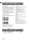
3.4 Setting the crossover frequencies
The use of extremely high-grade potentiometers made it unnecessary to install
xed-frequency plug-in modules. Thus, you have a wide range of setting options
available that even more expensive crossover networks hardly give you.
The CX3400 works in two specic frequency ranges: 44 though 930 Hz and 440
Hz through 9.3 kHz. The Linkwitz-Riley lters employed in the SUPER-X PRO
feature a slope of 24 dB/octave. High-grade components such as 1%-tolerance
metal-lm resistors ensure a perfect phase and amplitude response at all
crossover frequencies.
Please consult the manufacturer’s specications of the various speaker
components to set the crossover frequencies. When polar plots of specic
speakers or horns are available, use them too. Don’t set the crossover frequencies
around peaks or drop-outs in the frequency response, but try to nd a range that
is largely linear. When folded woofer horns are used, you also need to take the
horn length into account (see chapter 3.5 “Runtime Correction”).
◊ Never operate speaker/horn drivers below the frequency range
specified by the manufacturer!
3.5 Runtime correction
3.5.1 Background
The ideal transducer would be a point source of sound, i.e. a speaker of innitely
small dimension, which could still reproduce the entire frequency spectrum.
Unfortunately, such a sound source is impossible in reality, so that we have
to accept some compromises.
If the drivers in a multi-way system (i.e. the diaphragm set in motion by the voice
coil, but not e.g. the opening of a horn) are not exactly aligned on a vertical axis,
the varying distances between sound source and listener result in phase errors
and cancellations (also called “comb lter eect”). In particular, in the high-
frequency range it is imperative, due to the shorter wavelengths, that the drivers
be positioned one above the other, not side by side. The old-fashioned horizontal
rows of radiators follow this principle: while the speaker power is summed up
in the horizontal plane, the signals cancel each other on a vertical axis. Thus,
unwanted reections from the ceiling can be reduced.
Consequently, a speaker stack whose systems radiate towards the same area
should have all speakers arranged in a vertical line. And even if the front sides
of all systems are perfectly aligned, runtime dierences still occur due to the
dierent speaker designs (horns, bass reex cabinet, etc.).
The BEHRINGER SUPER-X PRO allows you to delay the Low bands by up to
2 milliseconds. In this way, you can virtually push back a specic speaker cabinet
by as much as 68.6 cm (which is quite useful, for example, when you place
a constant-directivity horn (CD) on top of a closed speaker cabinet).
Runtime correction is not the same as phase correction. Speaker systems that
have the same run times are also in phase (unless, the polarity of one speaker
is reversed). However, the opposite is not true.
3.5.2 Basics of electronic runtime correction
It is important to know how the dimensions of time and space are connected
with each other, e.g. by using a tape measure and a pocket calculator.
Example: a delay of 2 ms corresponds to a distance of 68.6 cm; when you measure
an oset of 30 cm you can calculate the necessary delay as follows:
2 ms x 30 / 68.6 = 0.87 ms.
If it is impossible to measure the oset with an accuracy of at least 1 cm, you can
perform the runtime correction with the help of a measuring microphone and
tunable sine generator, using the SUPER-X PRO’s feature of variably adjustable
crossover frequencies. More on this below.
The speed of sound is 343 m/s or 34.3 cm/ms approximately (hence, 2 ms of
delay correspond to a virtual speaker oset of 68.6 cm). Frequency is measured in
oscillations per second (1/s); the unit of measurement is Hertz (Hz).
For example, when you adjust a crossover frequency of 3 kHz between the horn
and midrange systems, the wavelength λ is calculated as follows: λ = c / f
(c = speed of sound; f = frequency). So, the wavelength at 3 kHz is:
34, 3 cm/ms
3000 1/s
34300 cm/ms
11, 43 cm
3000 1/s
= =
With a virtual distance of 68.6 cm, the control range of the potentiometer will
provide at least six positions that ensure phase coincidence. Perhaps none of
these positions will correct the runtime dierences completely, for example,
if the oset between the drivers is greater than 68.6 cm.
Is that important? It is, because only a system whose runtime dierences have
been corrected will be capable of:
1. reproducing pulse peaks correctly.
2. maintaining phase coincidence when the signal frequency moves away from
the crossover frequency.
3.5.3 Runtime correction in a P.A. system using the
SUPER-X PRO midrange/high midrange/tweeter range
Before you perform the following steps to correct both runtime and phase,
you should measure the oset between the drivers in cm and move the cabinets
(or delay their bands), until you think they are aligned correctly. This will save
you a lot of time later on. Now, do the ne adjustment as follows:
Using an analyzer
• Use pink noise as your sound source and connect the measuring microphone
to the measuring input of the analyzer.
• Adjust the bands below/above the crossover frequency so that each
one alone produces a 0 dB reading at the crossover frequency; mute the
remaining bands. If both bands together produce a +3 dB reading, they can
be considered in phase.
• Now, raise the crossover frequency by a factor of 1.5 and perform the same
steps as above. Here, too, the analyzer should read +3 dB.
• Finally, check your setting by raising the crossover frequency by a factor
of 1.4.
• Here, too, you can temporarily reverse the phase of one of the bands and
check the sound for cancellations. If no runtime correction is achieved
• Check whether the distance between the two drivers is or could be greater
than 68.6 cm. If so, try to correct it by moving the speaker cabinets.
• If this still doesn’t solve the problem, one of the bands could be reversed in
polarity. Experiment with the front-panel PHASE INVERT button.
Subwoofer/Woofer/Midrange
It is often claimed that phase or runtime correction below 150 Hz is unnecessary,
because the sound waves feature a spherical dispersion pattern at such low
frequencies. We disagree with this view.
Modern systems often use bass reex cabinets for their woofer or subwoofer
systems. Consequently, when stacking the cabinets, the drivers are usually
aligned along the vertical axis of the speaker front, or can at least be aligned
using the available control range of the SUPER-X PRO. Here, runtime correction
follows the same principle as in midrange/high-midrange/tweeter systems.