


7 SUPER-X PRO CX3400 User Manual
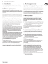
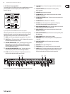
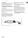
Fig. 2.4:
(1) (3) (5)(2) (6) (8) (9) (10) (12) (13) (14) (15)
Active control elements on the rear panel of the SUPER-X PRO for 2-way stereo operation
(1) Use the enclosed power cord to connect the unit to the mains.
(2) FUSE HOLDER / VOLTAGE SELECTOR. Please make sure that your local
voltage matches the voltage indicated on the unit, before you attempt to
connect and operate the CX3400. Blown fuses may only be replaced by fuses
of the same type and rating. Some models allow for inserting the fuse
holder in two dierent positions, in order to switch over from 230 V to
115 V operation, and vice versa. Please note that for 115 V operation
outside Europe, you need to use a fuse of a higher rating
(see chapter 4 “Installation”).
(3) and (10) HIGH OUTPUT connector. Output for the High band signal.
(5) and (12) LOW (LF SUM) OUTPUT connector. Output for the
Low band signal.
(6) and (13) XOVER FREQ. button. This button serves to switch over the control
range of the front-panel LOW/HIGH OVER FREQ. control from 44 to 930 Hz
or 440 Hz to 9.3 kHz.
◊ Always switch off the entire system before you press this button,
as it produces heavy interference noise that could damage your
speakers and/or other equipment.
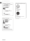
(8) MODE button. In stereo 2-way mode, the rst button must be pressed,
the second released. Please observe the labels on the rear panel of the unit.
◊ Always switch off the entire system before you press this button,
as it produces heavy interference noise that could damage your
speakers and/or other equipment.
(9) LOW SUM button. In stereo mode, the two Low paths can be summed
with the LOW SUM button and routed to the Low output of channel 1,
which is particularly useful in systems using additional subwoofers.
(14) INPUT connector. Input signal connector.
(15) SERIAL NUMBER. Please take the time to have the warranty card lled out
completely by your specialized dealer, and return it within 14 days after the
date of purchase, so as to be entitled to benet from our extended warranty.
Or use our online registration option available on the Internet
at behringer.com.
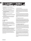
2.3.2 Stereo 3-way operation
First, activate stereo 3-way mode by means of the two MODE buttons on the
rear panel. The STEREO-LED on the front panel, above the LOW CUT button in
channel 2, lights up.
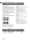
Fig. 2.5: Proper selection of the two MODE switches for stereo 3-way operation
Subsequently, the LEDs above the active controls on the front panel light up,
signaling which controls are active in the operating mode you just selected.
The functions of these controls can be seen from the second strip label.
In stereo mode, both channels perform the same functions.