


12 SUPER-X PRO CX3400 User Manual
Problems will be encountered only with unconventional setups (e.g. when the
woofers are placed underneath the stage, while the midrange/tweeter systems
are own above it) or when long woofer horns are used. The latter are the subject
of the following discussion.
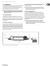
First, measure the horn length. In the case of folded woofer horns this is anything
but easy. Use a design drawing or open the cabinet (usually, a ap or cabinet side
wall can be opened easily, for instance, to replace a defective speaker).
We use a horn length of 1 m as an example. It will make no sense to delay the
signal, because the woofer signal arrives with a 3-ms delay at the “mouth”
of the horn. So, you cannot achieve a correct runtime, unless you would
delay the runtime of the remaining systems in the stack. The pulse response
(the main reason for runtime correction), however, is mainly determined by the
mid and tweeter ranges. What you can – and should – achieve though is phase
coincidence at the crossover frequency. Which is exactly what the SUPER-X PRO
gives you: free adjustability of the crossover frequency.
Calculate the frequency whose wavelength corresponds to twice the horn length.
At this frequency the output signal will be reversed by 180° in phase when it
comes out from the horn.
The frequency can be calculated as follows:
c
f (see chapter 3.5.2)
λ
=
Use the known values (speed of sound in m/s; horn length in m) to calculate
the frequency:
343 m/s
171, 5 1/s = 171, 5 Hz
2 x 1 m
=
Now, using a crossover frequency of 171.5 Hz and reversing the polarity
of the woofer output will result in an approximate phase correction,
which can be ne-adjusted by applying some delay or shifting the
crossover frequency a bit.
General remarks on runtime correction
Only one speaker stack each should be measured and corrected. Begin with the
highest crossover frequency and work your way downward.
◊ Once you have completed the runtime correction procedure,
please make a note of the relative positions of the speaker,
the adjusted crossover frequencies, delay times, etc. as well as of all
level settings (limiters included). The next time you set up your system,
you can start from these settings and with a bit of luck you will need
to make just a few fine adjustments, before you can turn to the EQs.
◊ Never drive different speakers from the same output! The distances
which the sound waves travel before they reach the listener will very
likely be different and unavoidably lead to phase shifts. Additionally,
the built-in drivers may have different efficiencies, impedance
characteristics or even reversed polarities.
When the speaker oset is greater than 68.6 cm you can only move the speaker
cabinets. Runtime correction is not the same as the signal delay applied to oset
groups of speakers. Here, the entire signal must be delayed by a much greater
amount (a suitable delay circuit is included, for example, in the BEHRINGER
ULTRA-CURVE DSP8024).
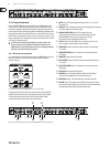
3.6 The limiters of the SUPER-X PRO
Limiting the signal in the crossover network is the last resort to protect the
system against overloading. Otherwise, improper handling by the user could lead
to serious damage in several drivers.
Each frequency requires its own limiter/compressor control times. The higher the
frequency, the shorter the control times. In the SUPER-X PRO, the control times
for the single bands have been determined after long listening tests, in order to
achieve inaudible gain adaptation instead of hard limiting.
The limiter threshold can be set from -6 dB to OFF and acts on all six limiters at
the same time. Still, each limiter band works independently, with the LIM-LEDs
lighting up as soon as the associated limiter is activated.
Please note that the limiters in the SUPER-X PRO are no “hard ratio” limiters, i.e.
signal peaks can surpass the adjusted threshold by as much as 6 dB. Please make
sure that your system provides enough headroom.
3.6.1 Limiter setup
On condition that you are using power amps and speakers that are compatible
in terms of power rating, you should drive your amps under full load (i.e. 0 dB).
Use pink noise from your analyzer as a sound source, turn the limiter THRESHOLD
control to maximum and press the LIMITER button. Then, gradually cut back the
threshold until just a few LIM-LEDs start ashing. Now, the entire system gain is
limited to 0 dB.
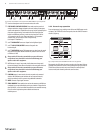
3.7 LOW SUM function
To produce a very loud and deep bass response, the lowest band should be
summed in a mono signal, while the remaining bands remain in stereo
(the human ear cannot locate the source of low frequencies). By combining all
woofer cabinets in one single cluster (the closer, the better) you can optimize
their eciency. Two woofer cabinets positioned next to each other produce an
SPL that is 3 dB higher than that of two cabinets placed at a certain distance.
Four cabinet give you as much as 6 dB, because low-frequency sound waves
feature a spherical dispersion pattern. When the cabinets are positioned
separately, the sound waves they radiate interfere with each other,
while cabinets placed next to each other create one common wave front
(compare two stones that are thrown into the water, either separately
or together).
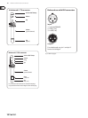
In stereo mode, the SUPER-X PRO can be switched to mono bass mode using the
LOW SUM button.
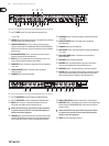
When the LOW SUM button is pressed, the low-frequency signal portions
in the left and right channels are summed up. The output signal is routed
to the Low output of channel 1, from where it can be used to drive, for instance,
a subwoofer cabinet.
3.8 CD HORN function
When a driver radiates into open space via a horn, its eciency increases.
Over the past few years, so-called constant-directivity horns have gained
widespread popularity, as they oer the advantage of producing a very
regular dispersion pattern over their frequency range; however, the higher
the frequency, the lower their eciency. To make up for this drawback,
the SUPER-X PRO includes a switchable pre-EQ for CD horns that ensures a at
frequency response even before equalization is applied. This pre-EQ raises the
signal gain by 3 dB at 3.5 kHz, which then increases by 6 dB/oct. up to 22.5 kHz.