


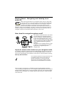
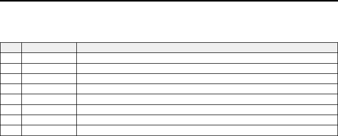
Connection overview ISO chamber B (loudspeakers), Fig. 3:
Note: The cable colors correspond to the VDO Dayton standard.
Pin Wire color Connection to loudspeaker
B1 Blue + Rear right (RR+)
B2 Blue/black - Rear right (RR-)
B3 Grey + Front right (FR+)
B4 Grey/black - Front right (FR-)
B5 Green + Front left (FL+)
B6 Green/black - Front left (FL-)
B7 White + Rear left (RL+)
B8 White/black - Rear left (RL-)
A
Use only loudspeakers of 4 Ohms impedance.
A
Do not connect the loudspeakers to earth.
A
Do not connect the booster/amplifier directly to the loudspeaker outputs.
A
Do not connect loudspeakers via an external fader.
Connections ISO chamber C, Fig. 4 - 6
■
Yellow connector C1 (line-out):
An
amplifier
with
additional
loudspeakers
can
be
connected
to
the
unit
via
this
connector.
–
Connect the “FRONT” lead to the front left (white) and front right (red) channel of
the amplifier.
–
Connect the “REAR” lead to the rear left (white) and rear right (red) channel of the
amplifier.
–
Connect the blue/yellow lead to the remote control (REMOTE) of the amplifier.
■
Green connector C2
Telephone input (adapter cable accessories):
Connect the loudspeaker output of the mobile phone or hands-free unit to the yellow
connector
at
the
end
of
cable
C2.
For
information
about
setting
the
telephone
attributes,
refer
to
“INITIALI
ZATION” ➽ Page 29.
■
Blue connector C3 (CD changer):
You can connect a digital AUDIOVOX CD changer to the unit. For further information
call AUDIOVOX technical support.
INSTALLATION INSTRUCTIONS
5