


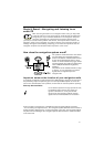
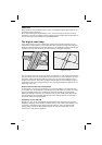
Connection overview, ISO chamber A, Fig. 2:
Note: The cable colors correspond to the VDO Dayton standard.
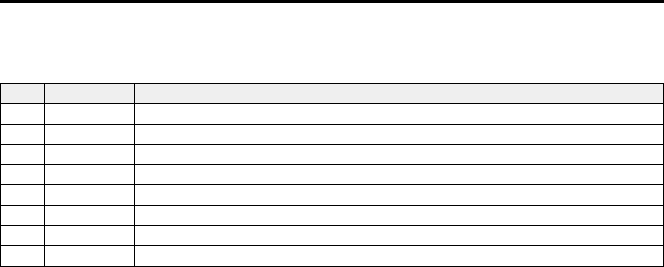
Pin Wire color Connection
A1 Orange Input speedometer signal / SDVC
A2 Green Switch input reversing signal (+12 volts)
A3 Purple Switch input telephone mute function
A4 Red/Yellow + 12 V permanent positive; terminal 30
A5 Blue Switch output for automatic antenna / relay motor antenna
A6 Grey Switch input pilot light
A7 Red +12 V ignition positive; terminal 15 (without switch-off on starting engine)
A8 Brown Battery negative; terminal 31
A
Only connect electrical signals to suitable connecting points in the vehicle.
A
If connection is made directly to the battery, protect the positive lead (red lead) with a
10 A fuse close to the battery (max. distance 10 to 15 cm).
■
Speedometer signal (A1):
Connect orange lead A1 to the vehicle speedometer signal. Refer to the vehicle-specific
data sheets for location and connection details (available on CD-ROM).
Note: Many vehicles are equipped with a speedometer signal on one of the radio
connectors. For further information contact your vehicle dealer or our hotline.
A
Never collect the speedometer signal from the ABS control!
■
Reversing signal (A2):
Connect green lead A2 to a suitable point of the reversing signal lead (positive lead of
reversing lamp).
■
Telephone mute function (A3), optional:
Connect purple lead A3 to the mute function output of the car phone or the hands-free
unit. When the telephone is in use, the radio is muted or the telephone conversation is
amplified via the car loudspeakers. See also “Green connector C2” on the following page.
■
12 V permanent positive (A4):
Connect yellow/red lead A4 to a suitable connector with 12 V permanent positive.
A
This connection should be rated for a current of at least 10 A.
■
Electronic antenna / motor antenna (A5), optional:
Connect blue lead A5 to the supply lead of an electronic antenna or to the control
lead of a power antenna.
A
Do not use this connection to supply the antenna motor.
■
Pilot lighting (A6), optional:
Connect gray cable A6 to a suitable connector of the low-beam positive lead. When
the low beam is switched on, the ring around the VOLUME - POWER button lights up,
even if the radio is switched off.
■
12 V ignition positive (A7):
Connect red lead A7 to a suitable 12 V circuit switched through the ignition.
INSTALLATION INSTRUCTIONS
4