


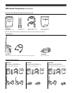
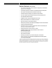
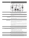
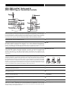
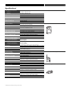
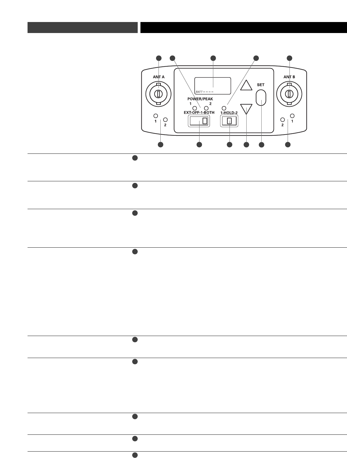
ATW-R1820 Dual-channel Receiver Controls (front panel)
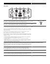
Liquid Crystal Display shows battery status and frequency settings. (Use the Dual-channel
Control Switch (6) to select frequencies for Receiver Channel 1 and Receiver Channel 2;
in Hold position, only Receiver Channel 1 frequency appears in LCD.) Battery meter is only
active when Dual-channel Control Switch is in the Hold position.
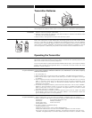
BNC-type antenna connectors. Antennas A & B (split internally) both provide signals for
Receiver Channel 1 and Receiver Channel 2. Attach the antennas to the antenna input jacks.
Make certain that during operation there is a clear open-air path between the receiver antennas
and the transmitters.
True Diversity operation: two antennas feed two completely independent RF sections on the
same frequency for each receiver; automatic logic circuitry selects the superior signal.
Diversity Indicator 1 indicates which tuner has the better reception and is in operation for
Receiver Channel 1; Diversity Indicator 2 indicates which tuner has the better reception and is
in operation for Receiver Channel 2.
Turns the unit on and off.
Choose “Ext”, if the unit is connected to an external power supply (12V DC source, 500 mA
nominal current, not included). In “Ext” position, both receiver channels and both outputs are
activated (indicated by illumination of Power/Peak LEDs 1 and 2).
Choose “Off” to turn the unit off.
Choose “1” to activate only a single receiver channel (Receiver Channel 1/Output A, indicated by the
illumination of Power/Peak LED 1). This conserves energy if you are only using one audio channel.
Choose “Both” to activate both receiver channels and both outputs (indicated by illumination of
Power/Peak LEDs 1 and 2).
Note: Selected receiver will be muted unless Dual-channel Control Switch (6) is in Hold position.
Indicates which receiver channel(s) is (are) in operation. Also indicates receiver overload by
turning off; too much signal will cause blinking LED (off during peaks). To correct overload,
adjust audio gain on transmitter. (See Audio Input Level (Gain) Adjustments, page 13.)
This switch allows you to use the single LCD window to control each of the two receiver
channels separately.
To set frequency for Receiver Channel 1, switch to 1 (left position).
To set frequency for Receiver Channel 2, switch to 2 (right position).
To lock settings and operate unit, switch to Hold (center position).
Note: Receiver Channel 1 is muted when switch is at 1; Receiver Channel 2 is muted
when switch is at 2; both channels un-mute when switch is at Hold.
This LED is red when switch is in position 1, indicating muted operation for Receiver Channel 1.
It is also red when switch is in position 2, indicating muted operation for Receiver Channel 2.
LED turns green in Hold position, indicating unit is ready for operation.
Use with the Dual-channel Control Switch and Up/Down arrows to choose operating frequencies
manually or automatically (using your choice of three automatic scan groups).
Press Up or Down arrows, in conjunction with the Set button, to choose operating frequencies
manually or automatically (using your choice of three automatic scan groups).
LCD
Antenna Input Jacks
Diversity Indicators
for each antenna
for each receiver
Power Switch
with four positions:
External, Off, 1, Both
Power/Peak LED
Dual-channel Control Switch
with three positions: 1, Hold, 2
Dual-channel Control LED
Set
Up/Down Arrows
1
2
3
4
5
6
7
8
9
2
3
6
1 7
2
3 4
5
6
9
8