


2
FRONT & REAR PANEL FEATURES
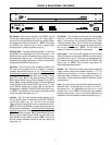
on
output 1 inputoutput 2
link port link
logic inputs
serial port
50/60 Hz
~
27V
12 watts
class 2 wiring
Atlas Sound LP
1601 Jack
McKay Blvd
Ennis, TX 75119
Made in U.S.A.
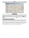
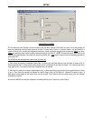
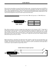
On Indicator: When power is applied to the MG2500, this red
LED will light indicating power to the unit is On. When power is
turned off, all current settings will be stored in non-volatile memory
and recalled when power is turned back on. NOTE: During setup
the MG2500 may instead be set to recall a special preset
whenever power is turned on (see Setup on pg. 10).
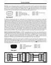
AC Power Cord: The power transformer provides 27 Volts AC to
the MG2500, and is detachable via a 5-pin DIN connector. The
MG2500
has two internal ‘self-resetting’ fuses (there are no user
serviceable parts inside the unit). If the internal fuses blow, they
will attempt to re-set after a short period. However, this may be an
indication that the MG2500
requires service.
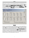
Serial Port: This 9-pin Sub-D (male) connector provides an RS-
232 Serial Port for remote control via computer or third-party
controllers (see RS-232 Control on pg. 13). The Serial Port has
the following pin assignments (left-to-right & top-to-bottom): Pin 1)
not used; Pin 2) Receive Data (RxD) input; Pin 3) Transmit
Data (TxD) output; Pin 4) Data Terminal Ready (DTR) output;
Pin 5) Ground; Pin 6) not used; Pin 7) Request To Send (RTS)
output; Pin 8) not used; Pin 9) not used. The default baud rate
for the Serial Port is 38,400 (See RS-232 Control on pg. 13). Atlas
Sound MG2500 software and a serial cable are provided for
programming via Windows
®
95/98/NT/2000/XP (see Setup on pg.
3). NOTE: The Serial Port can also transmit commands received
via the Logic Inputs (see Setup on pg. 10).
Link Port: This 9-pin Sub-D (female) connector provides a Link
Port for RS-232 control of multiple ATLAS SOUND
®
MG2500’s
(see RS-232 Control on pg. 13). The Link Port of one device
simply connects to the Serial Port of the next device (and so forth).
NOTE: All but the final MG2500 in a system should have the Link
Switch pressed in (see below). The Link Port has the following pin
assignments (right-to-left & top-to-bottom): Pin 1) not used; Pin
2) Transmit Data (TxD) output; Pin 3) Receive Data (RxD) input;
Pin 4) not used; Pin 5) Ground; Pin 6) not used; Pin 7) not
used; Pin 8) not used; Pin 9) not used. NOTE: The Link Port
will also transmit commands received via the Logic Inputs (see
Setup on pg. 10).
Link Switch: The Link Switch is used when connecting multiple
devices in a ‘Link Port to Serial Port’ configuration (see Link Port
above). From the factory, the Link Switch is released (out). When
connecting multiple devices, the Link Switch must be depressed
(in) on all devices except
the final device in the system (the device
with no Link Port connection). NOTE: The Link switch must
remain OUT when only a single device is being used.
Logic Inputs: This 25-pin Sub-D (female) connector provides
sixteen logic inputs for controlling the MG2500
via contact-closures
(see Logic Inputs on pg. 12). Logic Inputs are programmed using
the software and serial cable provided with the MG2500
(see
Setup on pg. 10). NOTE: From the factory, Logic Inputs 1~16
have no pre-programmed function.
Outputs 1 & 2: These plug-in barrier strips provide the balanced
analog line-level Outputs from processor Channels 1 & 2. For
balanced output, wire high to (+), low to (-), and ground to (
). For
unbalanced output, wire high to (+) and ground to (
), leaving (-)
unconnected. Signal level will be reduced by 6dB when outputs
are unbalanced.
Input: This plug-in barrier strip provides the balanced analog line-
level audio input. For balanced input, wire high to (+), low to (-),
and ground to (
). For unbalanced input, wire high to (+) and
ground to both (-) & (
). NOTE: The internal pink-noise generator
provides a second input. Input & noise may be assigned in any
combination to the two processing channels (see Setup on pg. 4).