


13
RS-232 CONTROL
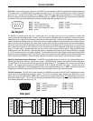
Serial Port: The 9-pin Sub-D (male) connector on the MG2500 rear panel provides the RS-232 compatible serial interface signals used
for computer control. The MG2500 Serial Port transmits serial data on pin 3 (TxD), receives serial data on pin 2 (RxD), and provides a
ground on Pin 5. The Data Terminal Ready (DTR) & Request To Send (RTS) output signals are connected to the +12 Volt power supply
(through a resistor) and are always asserted when the MG2500 power is on. NOTE: The Serial Port may also transmit commands which
are received via the Logic Inputs, depending upon the echo character assignments (see Setup on pg. 10).
pin #1 = not used
pin #2 = Receive Data (RxD) input
pin #3 = Transmit Data (TxD) output
pin #4 = Data Terminal Ready (DTR) output
pin #5 = ground
pin #6 = not used
pin #7 = Request To Send (RTS) output
pin #8 = not used
pin #9 = not used
serial port
54321
9876
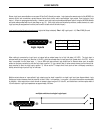
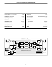
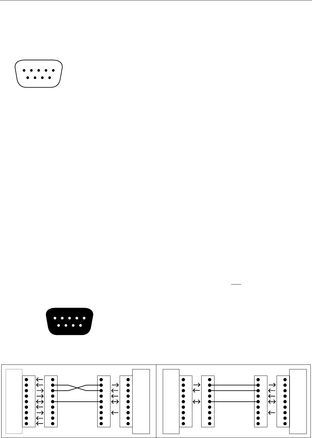
The MG2500 only requires receive data (pin 2), transmit data (pin 3), and signal ground (pin 5) to be connected for successful data
communications (see cable diagram below). However, the PC may require that signals be present on the data set ready, clear to send, or
carrier detect inputs, as well as the receive data, transmit data, and signal ground pins. Success or failure depends entirely on the actual
computer hardware and software being used. When trying to solve an interfacing problem, the most important thing to remember is that an
output of one device should connect to one or more inputs of the other device, and that two outputs should never be connected together.
Also, keep in mind that the RS-232 specification calls for the cable length to be no greater than 50 feet (although it is not unusual to be
able to operate over distances of 150 to 250 feet), and the connectors must be of the appropriate gender (male or female) to mate
properly. For best results, a shielded cable should be used, with the shield connected to chassis ground. Since the MG2500 serial
interface ground is also tied (indirectly) to the analog signal ground, undesirable ground loops may occur when the MG2500 is connected
to a PC (if the system grounding is not carefully designed). For best performance, the PC ground and the chassis ground of the MG2500
should be at the same potential, and the PC should get AC power from the same source as the MG2500 (and any other audio equipment
which is connected to the MG2500). Since most lap-top computers are isolated from earth ground, this should rarely pose a problem.
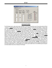
Serial Port Data Communications Parameters: The MG2500 communicates through the Serial Port at the factory selected rate of
38400 bits per second, with 8 data bits, 1 stop bit, and no parity. The MG2500 utilizes a subset of the standard 7-bit ASCII character set.
The eighth data bit of each character (the most significant bit) should always be 0. The computer should not echo the characters it
receives. The computer should not be set for either hardware (DTR) or software (XON/XOFF) flow control. The baud rate may be
changed to either 2400, 9600, or 19200 bits per second by means of the software (see Setup on pg. 3). NOTE: Baud rate may need to be
changed when the MG2500 is being used in RS-232 systems with other products having a lower maximum baud rate.
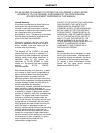
Link Port Connections: The 9-pin Sub-D (female) connector on the MG2500 rear panel provides the RS-232 compatible serial interface
signals used for linking multiple products within a system. The Link Port of one device simply connects to the Serial Port of the next
device, and so forth (see diagram below). NOTE: All but the final device in a system should have its ‘Link’
switch pressed in (see Front &
Rear Panel Features on pg. 2). The Link Port may also transmit commands which are received via the Logic Inputs, depending upon the
echo character assignments (see Setup on pg. 10).
pin #1 = not used
pin #2 = Transmit Data (TxD) output
pin #3 = Receive Data (RxD) input
pin #4 = not used
pin #5 = ground
pin #6 = not used
pin #7 = not used
pin #8 = not used
pin #9 = not used
link port
12345
6789
1
2
3
4
5
6
7
8
9
1
2
3
4
5
6
7
8
9
CD
RxD
TxD
DTR
DSR
RTS
CTS
RI
gnd
PC
(shield)
serial port
male female
1
2
3
4
5
6
7
8
9
1
2
3
4
5
6
7
8
9
n/a
RxD
TxD
DTR
gnd
n/a
RTS
n/a
n/a
MG2500
serial port
female male
Serial Cable
1
2
3
4
5
6
7
8
9
1
2
3
4
5
6
7
8
9
n/a
TxD
n/a
n/a
n/a
n/a
n/a
gnd
MG2500
(shield)
link port
female male
1
2
3
4
5
6
7
8
9
1
2
3
4
5
6
7
8
9
n/a
RxD
TxD
DTR
gnd
n/a
RTS
n/a
n/a
unit 2
serial port
female male
Link Cable
RxD