


8
SETUP
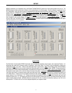
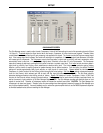
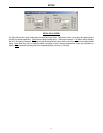
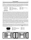
GAIN MATRIX #2 SCREEN
The Gain Matrix #2 screen provides a channel-to-channel (2x2) mix matrix (identical to Gain Matrix #1), which can be used to adjust the
amount of signal being routed from each channel to the other. From the factory, Channel 1 is routed to Output 1 only, and Channel 2 is
routed to Channel 2 only, providing two independent signal paths. Levels are adjusted by dragging the corresponding ‘faders
’ up or down.
‘Meters
’ are provided on each channel to display input/output levels at Gain Matrix #1. NOTE: For best performance, adjust levels so the
meters show occasional peaks in the yellow area, but never to the top (red). Invert
allows the phase of each corresponding signal path to
be reversed (180°).
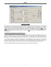
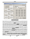
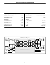
The MG2500 has two basic applications which utilize Gain Matrix #2
:
1) Each channel of processing is dedicated to either Input 1 or Noise signal, using Gain Matrix #1 (see Gain Matrix #1 screen on pg. 4).
Switching between Input 1 & Noise signals (to either Output) is then accomplished via Gain Matrix #2 presets. This is effective when only a
single output (zone), or two outputs (zones) with independent delay, are required.
2) Gain Matrix #1 presets can be used to switch between Input 1 or Noise signal being routed to either Output (see Gain Matrix #1 screen
on pg. 4). Each channel of processing is dedicated to a specific Output (zone), via Gain Matrix #2. Separate EQ presets for Input 1 &
Noise signals, as they appear at each output (zone), can also be used. This is effective when two outputs (zones), each with dedicated
processing, are required.
Of course, the MG2500 can simply be configured for processing Noise (or Input 1) signal only, at both Outputs.