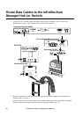
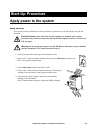
Start-Up Procedure: Apply power to the system
36 InfraStruXure System - Installation and Start-Up
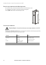
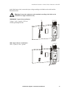
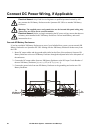
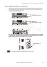
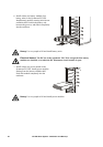
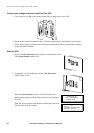
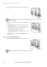
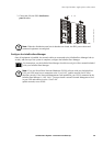
Verify bypass operation
Note: The H3 LED above the Q3 circuit breaker illuminates, but do not operate the circuit
breaker.
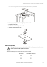
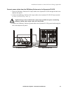
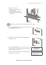
2. Use a true RMS voltmeter to make sure that there is no difference in potential between L1 IN and
L1 OUT, L2 IN and L2 OUT, and L3 IN and L3 OUT on the Q3 circuit breaker. The Q3 circuit
breaker must be in the OFF position. The top side of Q3 will be utility voltage and the bottom side
of Q3 will be the voltage from the UPS in static bypass. Voltage should be less than 2 volts.
Note: Q3 is a 4-pole circuit breaker. Be sure to measure L1 to L1, L2 to L2, and L3 to L3.
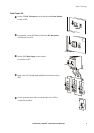
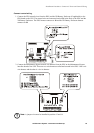
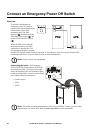
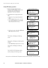
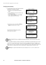
1. Command the UPS into static bypass operation
through the UPS display interface:
a. Press the
ESC key to open the top-level
menu.
b. Select Control on the top-level menu, and
press the
ENTER key.
Top-Level Menu
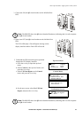
c. Select UPS Into Bypass on the Control
menu, and press the
ENTER key.
Control Menu
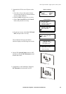
d. On the next screen: select Yes, UPS into
Bypass, and press the
ENTER key.
Confirmation Screen
The BYPASS LED illuminates and the
following screens appear:
Control
Status
Setup
Accessories
Logging
Display
Diags
Help
UPS Into Bypass
Do Self Test
Simulate Power Fail
Graceful Reboot
Graceful Turn Off
Start Runtime Cal
Turn Load On
Confirm
Yes, UPS into Bypass
No, Abort
UPS has been
commanded to go
into Bypass...
UPS load is in Bypass
Press any key...