


Contents
InfraStruXure System - Installation and Start-Up i
Safety ................................................................................ 1
IMPORTANT SAFETY INSTRUCTIONS
- SAVE THESE INSTRUCTIONS . . . . . . . . . . . . . . . . . . . . . . . . . . . . . .1
Symbols used in this manual . . . . . . . . . . . . . . . . . . . . . . . . 1
Warnings . . . . . . . . . . . . . . . . . . . . . . . . . . . . . . . . . . . . . . . . . . . . . . . .2
Installation/Maintenance . . . . . . . . . . . . . . . . . . . . . . . . . . . 2
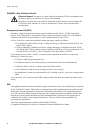
Maintenance performed while the PDU is receiving input power . 2
Total Power Off . . . . . . . . . . . . . . . . . . . . . . . . . . . . . . . . . 3
DANGER—Risk of Electric Shock! . . . . . . . . . . . . . . . . . . . . 4
Emergency Power Off (EPO) . . . . . . . . . . . . . . . . . . . . . . . . 4
EMI . . . . . . . . . . . . . . . . . . . . . . . . . . . . . . . . . . . . . . . . . 4
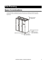
Site Planning .................................................................... 5
Space Considerations. . . . . . . . . . . . . . . . . . . . . . . . . . . . . . . . . . . . . .5
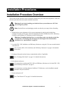
Installation Procedures ................................................... 7
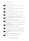
Installation Procedure Overview . . . . . . . . . . . . . . . . . . . . . . . . . . . . .7
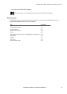
Tools Required . . . . . . . . . . . . . . . . . . . . . . . . . . . . . . . . . 9
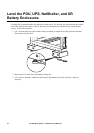
Level the PDU, UPS, NetShelter, and XR Battery Enclosures. . . . .10
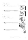
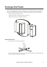
Exchange Side Panels . . . . . . . . . . . . . . . . . . . . . . . . . . . . . . . . . . . .11
Exchange Side Panels . . . . . . . . . . . . . . . . . . . . . . . . . . . 11
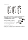
Connect Battery Enclosure communication cables . . . . . . . . 12
Join the PDU, UPS, and XR Battery Enclosures. . . . . . . . . . . . . . . .13
Connect Utility Conductors to the PDU. . . . . . . . . . . . . . . . . . . . . . .14
Access the PDU Main Input switch . . . . . . . . . . . . . . . . . . . 14
Attach conduit to the PDU for the input conductors . . . . . . . . 14
Install a circuit breaker . . . . . . . . . . . . . . . . . . . . . . . . . . . 15
Route the input conductors to the Main Input switch . . . . . . . 16
Connect input conductors . . . . . . . . . . . . . . . . . . . . . . . . . 16
Connect AC Power and Control Wiring. . . . . . . . . . . . . . . . . . . . . . .18