


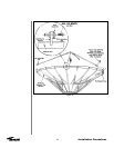
Reflector to
Ground Mount
Assembly
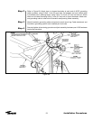
Step 1
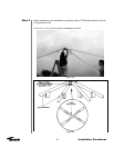
Step 2
48
Installation Procedures
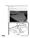
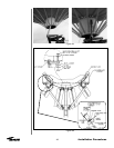
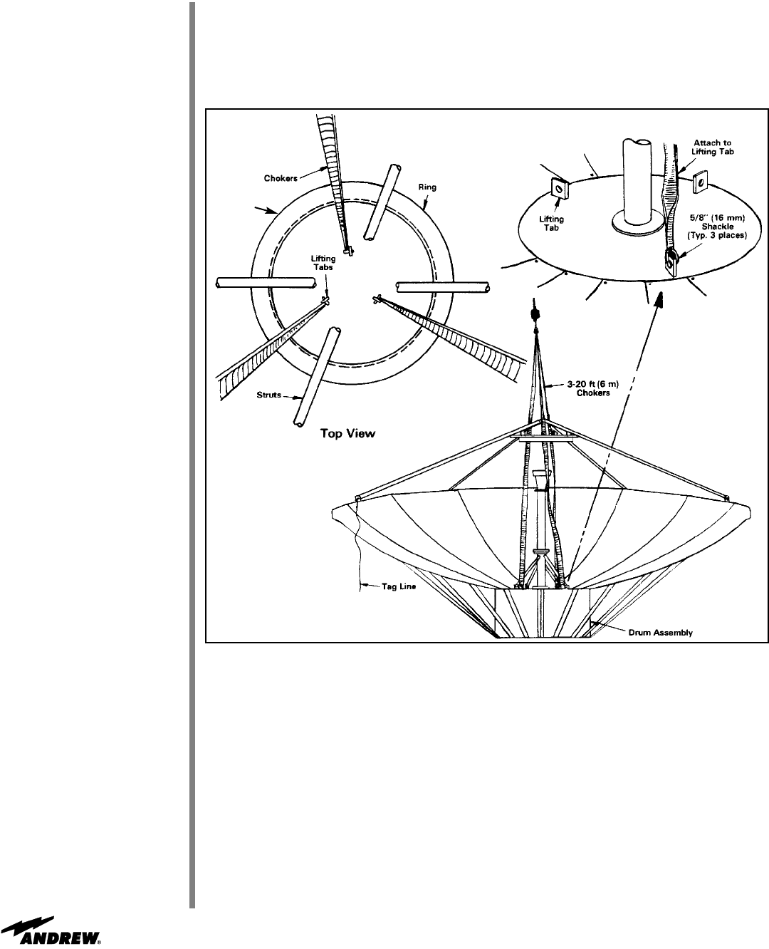
Attach 5/8 in (16 mm) shackles to three lifting tabs as shown in Figure 62. Attach 15 ft
(4.5 m) tag lines to opposing quadrapod plates.
Figure 62
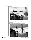
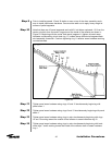
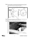
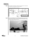
Raise reflector/backstructure assembly and align with corresponding mounting holes in
drum and elevation axis assemblies using tag lines for proper guidance as shown in
Figure 63. Attach rear of drum assembly to elevation axis assembly using 300037 spac-
ers, 3/4 x 4 in (102 mm) bolt and nut assemblies and flat washers. Align mounting holes
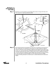
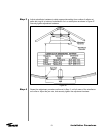
and attach forward leg of jack tripod to forward portion of drum assembly using 5/8 x 3
in (76 mm) bolt and nut assembly, clipped washers and cast spacer as shown in Figure
64. Securely tighten mounting hardware per A-325 Tensioning Procedure. Note:
Required mounting hardware is included as part of reflector/backstructure hardware kit
300033.
Top