


Step 2
Step 3
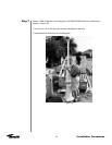
Step 4
37
Installation Procedures
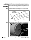
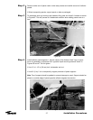
Remove entire end of panel crate to allow easy access and careful removal of reflector
panels.
• When transporting panels, support panel on side as packaged
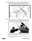
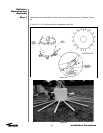
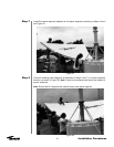
Tie assembly down by knotting rope between lifting tabs and three 3 ft stakes as shown
in Figure 45. This will prevent an unbalanced condition when adding panels one at a
time.
Figure 45
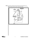
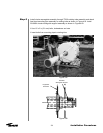
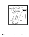
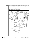
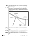
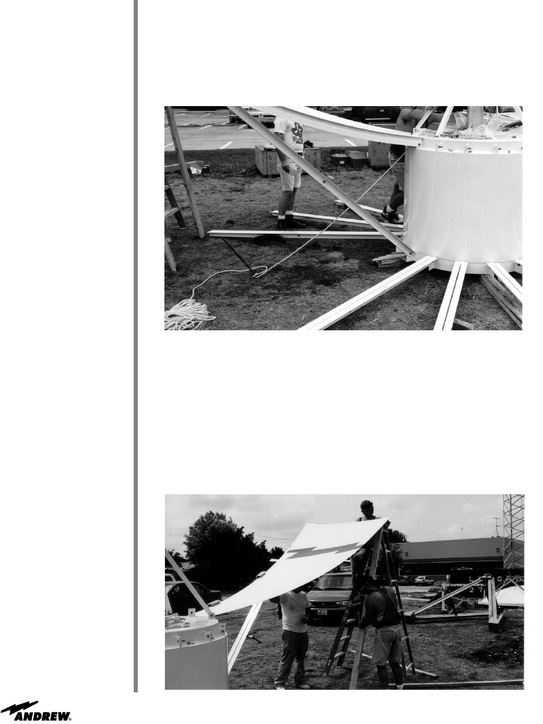
Install reflector panel segment 1 with the center of the Andrew “flash” logo to upper
drum ring assembly ring bracket 180° opposite tripod mounting holes as shown in
Figures 46 and 47. Do not tighten.
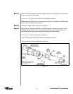
• Use 1/2 x 1-1/2 in (38 mm) bolt, lockwasher and nut
• Use 9 ft (3 m) 2 x 4 to temporarily support perimeter of panel segment
Note: Top of support should be padded to prevent damage to panel. Support should be
placed on outside edge of panel opposite reflector segment tee section.
Figure 46