


Step 9
Step 10
Step 11
Step 12
Step 13
Step 14
42
Installation Procedures
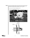
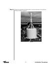
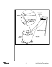
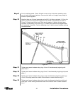
Prior to installing panels 15 and 16 station a man on top of the drum assembly enclo-
sure to install panel seam hardware. Care must be taken not to apply heavy weight to
surface of panel segments.
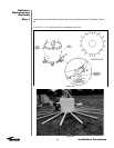
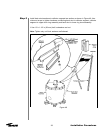
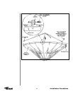
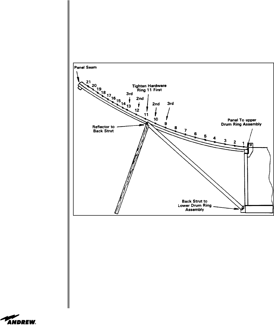
Note that there are 16 panel segments each with 21 bolt holes numbered 1-21 from the
center out which form concentric rings around the inside of the reflector as shown in
Figure 53. Beginning with the center flash panel (segment 1) tighten all panel seam
hardware corresponding to bolt hole ring 11, located above reflector tee segment/back
strut assembly connection. Continue tightening ring 11 reflector seam hardware working
counterclockwise.
Figure 53
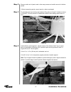
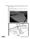
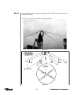
Tighten panel seam hardware along rings 10 and 12 simultaneously beginning with
panel seam 1.
Tighten panel seam hardware along rings 9 and 13 simultaneously beginning with panel
seam 1.
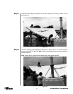
Tighten panel seam hardware along rings in pairs simultaneously beginning with rings
14 and 15 working toward the outside of the reflector to seam hardware ring 21.
Tighten panel seam hardware along rings in pairs simultaneously beginning with hard-
ware rings 7 and 8 working toward the inside of the reflector down to seam hardware
ring 1.