


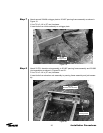
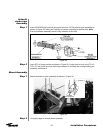

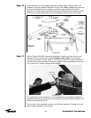
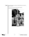
Step 7
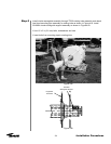
Step 8
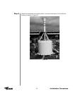
Step 9
28
Installation Procedures
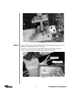
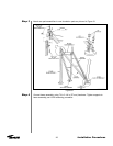
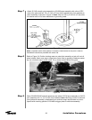
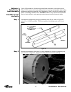
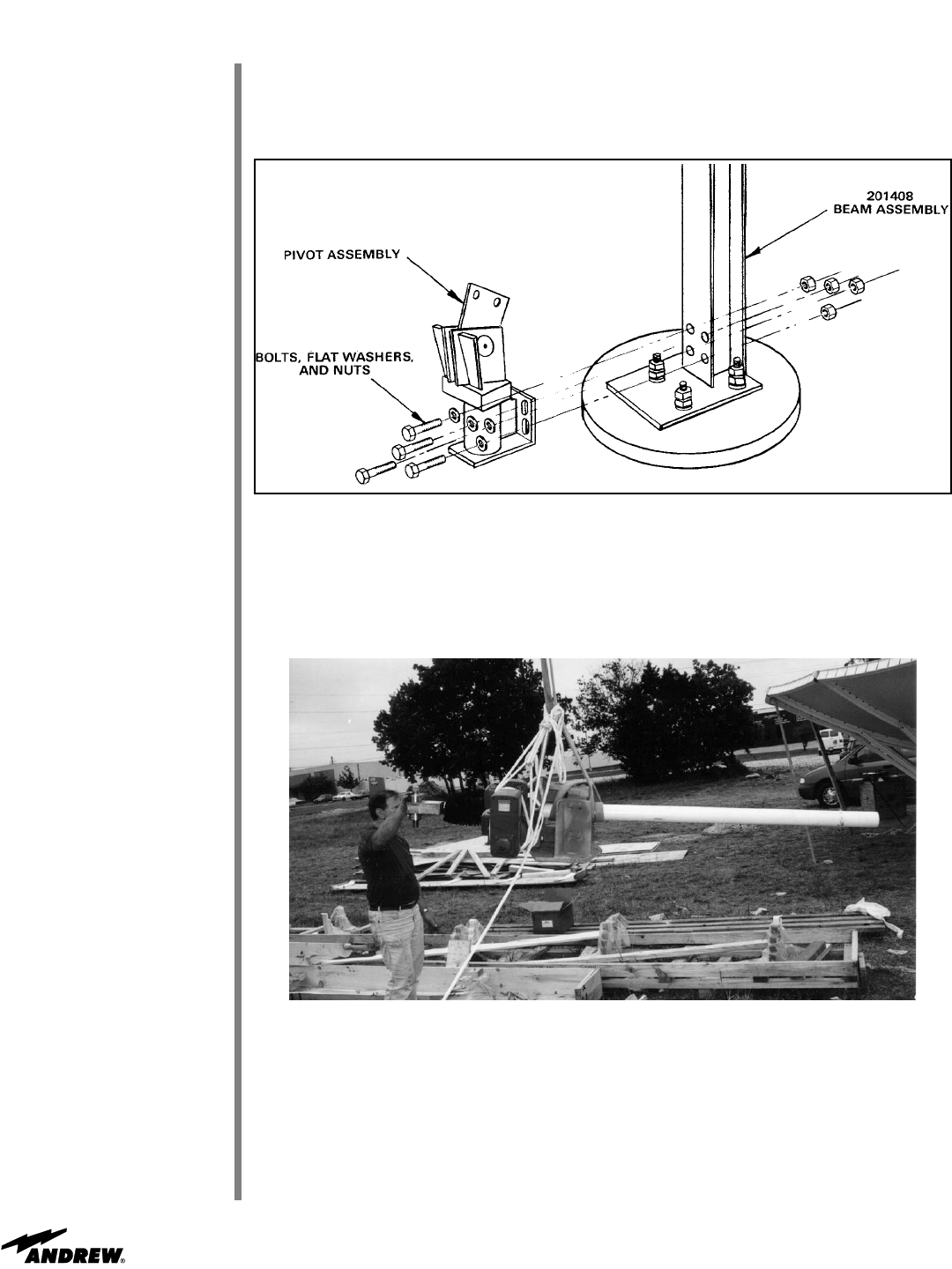
Figure 34
Raise 221923/223180 azimuth jackscrew and attach 221738 pivot assembly to 201273
joint assembly with 1 x 2-1/2 in (63 mm) hardware. Note: Mounting position of azimuth
pivot jackscrew assembly is dependent upon azimuth range requirements and corre-
sponds with mounting position of 201488 outrigger plate or extension assembly.
Note: If optional motor drive system is included, install motors at this point. Refer to
installation instructions provided with motor kits.
Refer to Figure 34. Position hoisting ropes on motor/jack assembly so jack will not roll
when hoisted. Attach one rope to large motor frame next to gearbox to balance assem-
bly; do not attach rope to small motor. Tie up loose conduit before lifting jack.
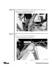
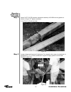
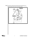
Figure 33
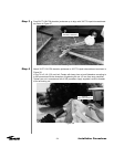
Attach 221345 azimuth pivot assembly to 201408 beam assembly with a line of RTV
around the plate and four 7/8 x 2-1/4 in (57 mm) holts inserted from pivot assembly to
beam assembly as shown in Figure 33. Note: Use one 7/8 by 2-3/4 inch (70 mm) bolt,
flat washer and nut for later attachment of grounding cable.
221345
7/8 x 2-1/4”
(57 mm)