


Step 10
Step 11
29
Installation Procedures
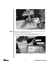
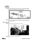
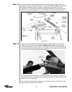
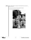
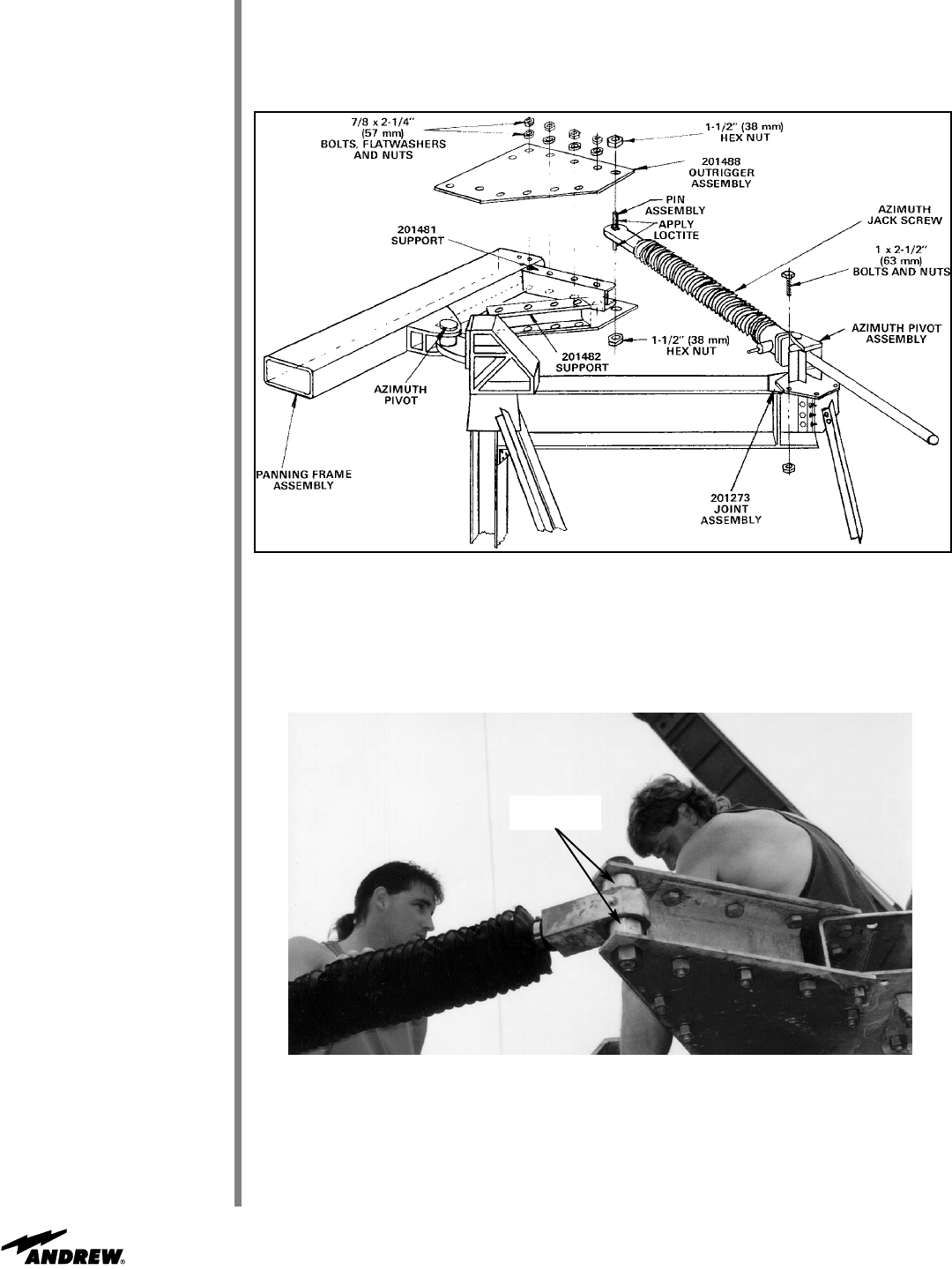
Extend jackscrew to meet outrigger assembly. Loosely attach outrigger plate to pin
assembly in azimuth jackscrew as shown in Figure 35A. Note: Realignment of panning
frame/pivot assembly may be necessary to ensure proper alignment of azimuth
jackscrew pin. Snug panning frame/pivot assembly hardware and fully extend azimuth
jackscrew to ensure binding does not occur throughout entire azimuth pivot range.
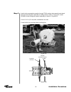
Figure 35A
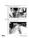
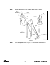
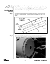
Refer to Figures 35A/35B. Loosen both setscrews in upper and lower collars of pin
assembly at end of azimuth jack. Do not retighten these collars. Apply supplied
Loctite to pin threads and nuts. Attach 1-1/2 in (38 mm) hex nuts to top and bottom of
azimuth jackscrew pin assembly and securely tighten mounting hardware using 6 foot
(1.8 m) lever arm. Tighten outrigger plate hardware.
221923/223180
221738
Figure 35B
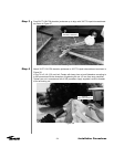
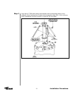
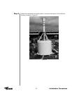
The tripod ground mount assembly is now completed with the necessary operational
essentials. All ground mount options have separate instructional bulletins located in the
parts kit that contain the option.
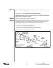
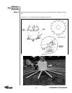
The next step in the installation process is the reflector assembly. Proceed to the next
page to begin installation of the reflector.
Upper and
Lower Collars