


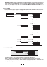
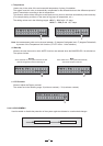
31
SEND
ACCEPT IGNORE
..
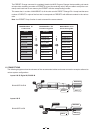
Preset #2
Preset #3
Preset #4
Preset #5
Preset #6
Preset #7
Preset #8
Preset #9
..
#2 MySetup
#3 MySetup5
#4 LiveSet1
#5 LiveSet2
#6 Monitor
#7 Monitor2
#8 Monitor3
#9 Side
..
..
#2 SideField
#3 Concert1
#4 Concert2
#5 Concert3
#6 Concert4
#7 Remote1
#8 Remote2
#9 Remote2
..
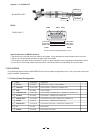
Preset Change RX
MAXIDRIVE3.4 #2
Load Preset
MAXIDRIVE3.4 #1
Preset Change RX
MAXIDRIVE3.4 #3
SERIAL
PORT
SERIAL
PORT
..
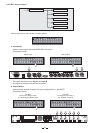
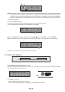
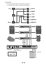
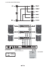
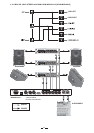
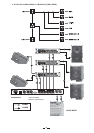
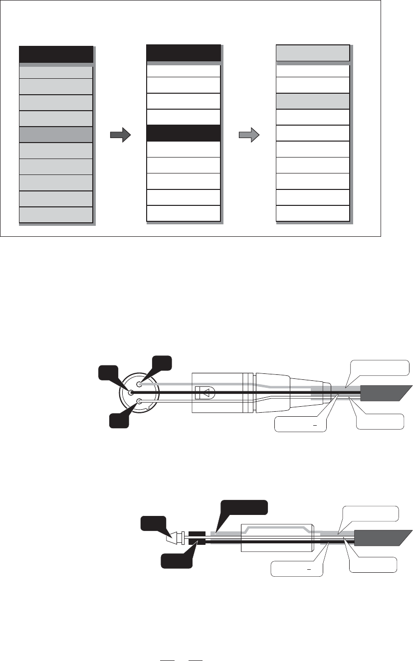
6. CONNECTIONS
The following diagrams show the schemes of the recommended cables and some connection examples referred to
various system configurations.
Inputs A & B, Digital IN, RS485 IN
3
1
2
GROUND
HOT (+)
COLD ( )
Inputs A & B
GROUND
HOT (+)
COLD ( )
RING
SLEEVE
TIP
BALANCED XLR-M
BALANCED JACK
The PRESET Change command is completely identical to MIDI Program Change: the transmitting unit sends
an instruction containing a number of PRESETS to load; the receiving units (if they are able to accept the com-
mand) each loads into its own memory the PRESET with the corresponding number.
This means that, in a chain of MAXIDRIVE3.4, all the units set with PRESET Change RX = Accept load the same
number of PRESET, in spite of the fact that it corresponds to PRESETS with different contents in the various
units.
Note: the PRESET Dump function is used to transmit the same contents.