


28
Chapter 2 - Connections
GTP-870HD Owner’s Manual
Room 2 Connections
Want to listen to a CD in the den while the kids are
watching a movie in the family room? Follow these
steps to connect the GTP-870HD to a sound system
in a second room.
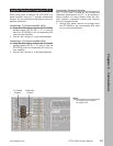
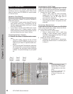
Variable or Fixed Output?
Before you connect your Room 2 sound system, you
need to determine whether to use the Variable or
Fixed audio outputs:
• If your Room 2 sound system does NOT have its
own volume control (e.g., an amplifier), use the
Variable outputs and adjust the Room 2 volume
from the GTP-870HD.
• If your Room 2 sound system DOES have its own
volume control (e.g., a stereo receiver or other
audio component), use the Fixed outputs and ad
-
just the volume from the Room 2 device.
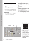
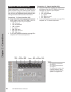
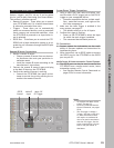
Connecting the Zone 2 Outputs
1 Connect the Room 2 amplifier/audio compo
-
nent.
• Using RCA cables, connect the Var or Fixed
outputs on the GTP-870HD to the line or aux
inputs on your Room 2 amplifier/audio com-
ponent.
• If you are using the Fixed outputs, make sure
the volume level on your external component
is turned all the way down before switching
to Room 2 to prevent damage to your speak-
ers.
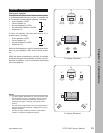
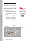
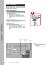
Connecting the 12V DC Trigger
If your external device is equipped with a 12V DC
trigger, you can have the device power on automati-
cally when you select Room 2 from the GTP-870HD.
1 Connect the 12V DC trigger.
• Using a cable with two mono mini-plugs,
connect the 12V DC trigger jack from the
GTP-870HD to the 12V DC trigger jack on
your external component.
• Now when you press the Room 2 button, the
sound system in Room 2 will power on auto-
matically.
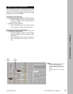
Connecting a Remote Sensor
If you want to be able to control the GTP-870HD
while in the second room, simply connect an IR sen
-
sor to the Zone 2 remote input.
1 Connect the Zone 2 remote sensor.
• Using a remote sensor with a cable long
enough to reach between rooms, connect
the cable’s mini-plug into the Zone 2 IR input
jack on the GTP-870HD.
2 Attach the remote sensor in Room 2.
• Following the manufacturer’s instructions,
attach the remote sensor in a suitable place
in Room 2.
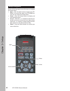
Notes:
• To switch to Room 2 mode,
press the Rm 2 button on the
remote control, or the Room
2 On/Off button on the front
panel.
• For Room 2 configuration set-
tings, see pages 41-42.
• For Room 2 operations, see
page 62.
Zone 2
Variable
Output
Zone 2
Fixed
Output
Zone 2
12V DC
Trigger
Zone 2
IR Input