


ADCP-75-214 • Issue 2 • September 2006
Page 20
© 2006, ADC Telecommunications, Inc.
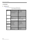
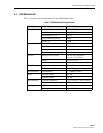
5.3 PDU (Power Distribution Unit)
Table 4 provides typical specifications for the PDU.
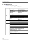
Table 4. Power Distribution Unit (PDU) Specifications
CATEGORY PARAMETER SPECIFICATION
Electrical Input voltage range 20–56VDC positive/negative ground
(Input polarization protected)
Output voltage 15V, 4% (Over voltage protection)
Output voltage accuracy 4% in 20mA – 400mAMAX 10% in 1.5A
Output ripple 100mV pk – pk
PDU Inrush Current ETS300132-2, Part 2
Short circuit protection 1500mA, 10%
Connector and
LED
Outputs for TMA's SMB connector Male (3 pcs)
Input connector Molex Micro-fit 43045 - 0400
General alarm connector Molex Mini-Fit 39-30-3035
Communications link between BTS
and RET
Molex Mini-Fit 39-30-3035
Indicators Two color LED (3 pcs) (green and yellow)
Red LED 1 pcs
Physical Dimensions (W x H x D) 194.4 x 43.6 x 100.0 mm
(7.7 x 1.7 x 3.9 inches)
Weight 0.5 Kg (1.2 lbs.)
Color Gray Metallic
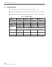
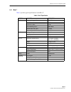
Communication Pin Number Signal Comments
1 RS485 A RET control command AISG Layer2. ISO/
IEC 8482:1993 (RS485).
2RS485 B
3 RS485 GND
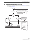
PDU only receives control command from BTS and modulates 2.176MHz Modem
Signal and transmit to TMA through SMB connector, and vice versa.
Resistance between RS485 A and
RS485 B
> 1k Ohm
Resistance between RS485 A or
RS485 B and DC return / RS485 GND
> 1k Ohm
Capacitance between RS485 A or
RS485 B
< 1nF
Capacitance between RS485 A or
RS485 B and DC/RS485 GND
< 1nF