


ADCP-75-214 • Issue 2 • September 2006
Page 10
© 2006, ADC Telecommunications, Inc.
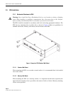
2.4 Bias-T Installation
2.4.1 Mechanical Attachment and Cable Connections
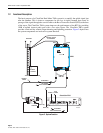
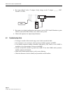
The Bias-T is installed either inline with the antenna feeder cable or directly to the BTS antenna
port. Integrated lightning protection is built into each Bias-T unit. There is no additional
mounting hardware required. Bias-T can be installed in either of the two antenna feeder cables
for each MHU. Connect the Bias-T as follows:
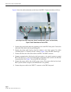
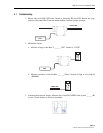
1. Connect the Bias-T “BTS” connector inline with the antenna feeder cable or directly in the
BTS antenna port.
2. Connect the coaxial run going to the MHU to the “ANT” port of the Bias-T.
3. Connect the mini coax cable to the TNC connector of the Bias-T unit.
4. Connect the other end of the mini coax cable to the PDU front panel SMB connector
MHU1…3 (whichever is being used).
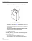
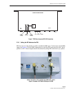
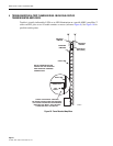
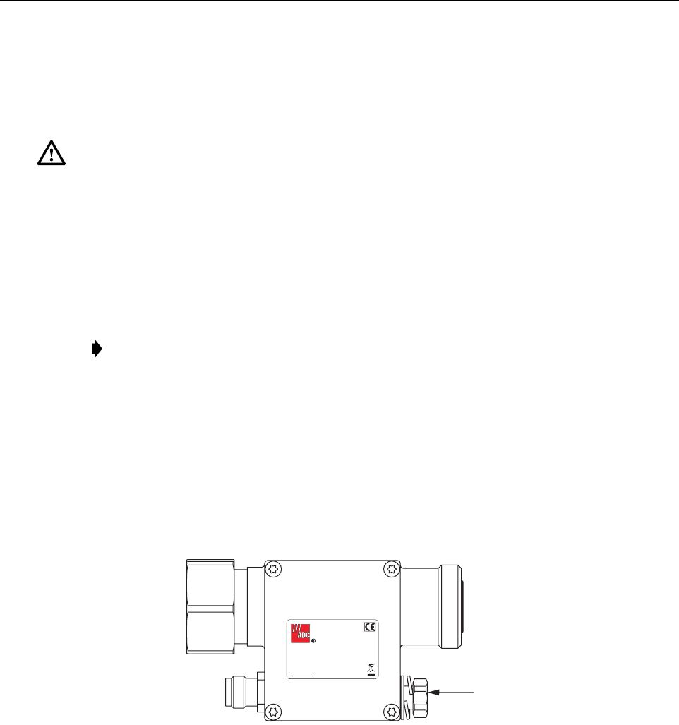
5. Connect the ground cable to the Bias-T ground terminal (see Figure 9).
6. Connect the other end of the ground cable to the site-grounding pole.
Figure 9. Bias-T Ground Cable Connection
2.4.2 Additional Lightning Protection
ADC recommends that the operator install further lightning protection between the MHU and
Bias-T. It must allow the DC voltage to pass through the lightning protector, if it does not then
the Bias-T should be mounted on the antenna side of the protection.
Caution: Prior to installing any Bias-T unit, ensure that the BTS transmitter output is turned off
and that precautions are taken to ensure that the transmitter cannot be activated during the
equipment installation.
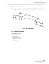
Note: Orientation of the Bias-T is critical, BTS end should face the BTS and ANT should
face the antenna.
BTS ANT
DC
Bias-T kit
Freq: 800 - 2200MHz
Temp: -40 to +65 C
Input: 5 to 24VDC
Max Current: 2A
P/N: 1344027
S/N: XXXXXXXXX
Date: YYYY/MM/DD
ASSEMBLED IN
KOREA
GROUND TERMINAL
21298-A