


ADCP-75-214 • Issue 2 • September 2006
Page 9
© 2006, ADC Telecommunications, Inc.
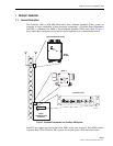
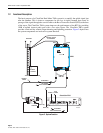
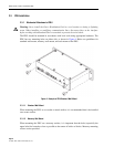
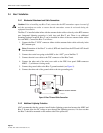
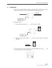
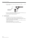
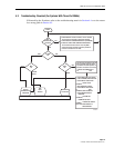
Figure 7. PDU Alarm Logic and RS-485 Connections
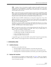
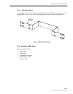
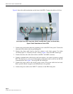
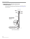
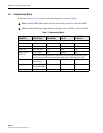
2.3.3 Setting the DIP Switch on the PDU
PDU has one set of dip switches to enable or disable the MHU ports. To disconnect unused MHU
output (see
Figure 8
). For the MHU outputs that are used, the DIP switch must be in the “down”
position or “ON”. Unused outputs must be disconnected by setting DIP switch in the “up” position.
(Switch 1 and 3 Set to “ON” to Indicate Use of MHU Ports 1 and 3)
Figure 8. Example of DIP Switch Setting on the PDU
RS485A RS485B
POWER DISTRIBUTION UNIT
DC
INPUT
PDU
ALALRM
LOG IC
NO
(NO RMALLY
OPEN)
COM
(CO MMO N)
NC
(NOR MA LLY
CLOSED)
OUTPUT
GND
21307-B