


ADCP-75-214 • Issue 2 • September 2006
Page 16
© 2006, ADC Telecommunications, Inc.
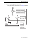
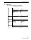
4.4 Troubleshooting Matrix
If directed in Section 4.3 to consult a troubleshooting matrix, see Table 1 below.
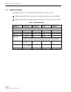
Note: ClearGain PDU DIP switches must be in the down position for each active MHU!
Note:
ClearGain PDU input voltage must be in the range –56 to –20 VDC or +20 to +56 VDC.
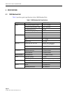
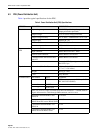
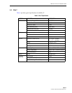
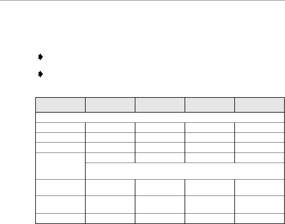
Table 1. Troubleshooting Matrix
PARAMETER SPECIFICATION EXPLANATION
GREEN/YELLOW
OK LED
RED GENERAL
ALARM LED
Electronic Load
Each Path OFF < 180 mA Fail OFF ON
Each Path ON 180 – 220 mA OK GREEN OFF
Total Fail 370 – 400 mA Fail OFF ON
Short Circuit
Protection
1.5 A ± 10% Fail GREEN ON
Short state of MHU path does not affect other path. After generating Green alarm,
the short state is held for ten seconds then Red alarm is generated by the PDU.
Circuit Fluctuation Min 180 mA
Max 380 mA
One path failed. YELLOW ON
Input Voltage
–56 to –20 VDC /
+20 to +56 VDC
OK GREEN OFF
Output Voltage 15 V, 4% Total failure. OFF ON