


ADCP-75-214 • Issue 2 • September 2006
Page 8
© 2006, ADC Telecommunications, Inc.
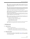
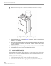
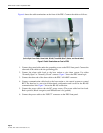
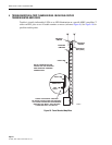
Figure 6 shows the cable terminations on the front of the PDU. Connect the cables as follows:
(Left to Right: Power Cable, Alarm Cable, RS-485, Three MHU (Bias-T) Cables, and Ground Cable)
Figure 6. Cable Terminations on Front of PDU
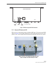
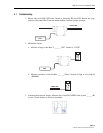
1. Connect the ground cable under the grounding screw on the PDU front panel. Connect the
other end of the cable to the site-grounding pole.
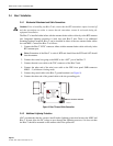
2. Connect the alarm cable leads to the base station or site alarm system. Use either
“Normally Open” or “Normally Closed” contacts. Figure 7 shows the PDU alarm logic.
3. Connect the other end of the alarm cable to the PDU “ALARM” connector.
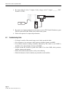
4. Connect communication cable leads to the base station or site control systems to control
RET. The data bus is a two-wire bi-directional configuration and is used for the RS-485
communications link. Figure 7 shows the RS-485 connection.
5. Connect the power cable to the site DC power source. (The power cable has four leads.
Red is positive, Black is negative, and White/Green is for ground.)
6. Connect the power cable to the “INPUT” connector on the PDU front panel.