


10
STEP 3: POWER UP PROCEDURE WITHOUT M1002A BOARDS
It is extremely important that you never power up an AP3400 with the interconnecting cablesbetween the circuit
boards not connected.
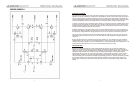
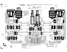
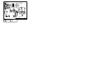
Time and possible further damage will be reduced if you test M1011A and M1002A boards separately. To do this you
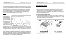
must use the M1011A and M1002A test connecters. These are shown in figures #5 and #6. These can be made if the
Molex connector parts are available or order them from the Yorkville Service Parts Dept. With the test connectors
connected to every board, slowly variac up the line AC voltage.
NOTE:
It may be simplier to remove the power supply connections to M1002A boards not being troubleshooted to
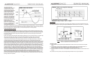
reduce the possibility of further damage. With the M1011A test connector connected, a sinewave can be passed
through the board and be seen on test points 5 and 6. With the M1002 Atest connector installed, static DC
measurements can be made. A slight DC offset may be present on the board?s output as there will not be any DC
correcting feedback.
STEP 4: DISMANTLING AND REASSEMBLY PRECAUTIONS
A.
When removing power supply wires or resoldering wires to eyelets on the M1011A board, double check that there
are no solder bridges or icicles bridging traces or other eyelets. Failure to do so will result in the destruction of
newly installed boards as well as other boards in the unit. Also make sure wire color codes are correctly oriented
in their proper eyelets, and be careful that ribbon cables don?t get pinched or cut under the M1011A board.
B.
When reinstalling M1002A boards, make sure the output wires, i.e. the red and yellow signal and black ground
wires, are not reversed. If either or both channels are reversed, the amp will stay in protect mode with the red
protect LED staying on or sampling on and off.
11
SPECIFICATIONS
POWER
•
All values are in WATTS at 1KHz, except FTC 20Hz-20KHz.
•
Measurements made with regulated 120 VAC sine wave at line cord.
•
All values are rounded down to the nearest 25 watts
BURST AVERAGE
Measured as a 2 cycle burst at 1KHz, 8:1 duty. (Continuous measurements may require line currents >15 Amps).
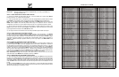
ONE CHANNEL DRIVEN (WATTS).
LOAD CONT. AVG. BURST AVG. PEAK INSTANT FTC 20-20KHz
8 ohms 900 1250 3000 800
4 ohms 1500 2250 6000 1200
BOTH CHANNELS DRIVEN (WATTS).
LOAD CONT. AVG. BURST AVG. PEAK INSTANT FTC 20-20KHz
8 ohms 750 1200 3000 650
4 ohms 1200 2175 6000 950
BRIDGED (WATTS)
LOAD CONT. AVG. BURST AVG. PEAK INSTANT FTC 20-20KHz
16 ohms 1500 2400 6000 1300
8 ohms 2400 4350 12000 1900
THD DISTORTION
LOAD AT 1KHz 20Hz - 20KHz
8 ohms <0.003 % <0.04 %
4 ohms <0.004% <0.05 %
CROSSTALK:
-75 dB below full power at 1KHz
-60 dB below full power, 20Hz - 20KHz
INPUT IMPEDANCE:
20K ohms balanced, 10 Kohms unbalanced
INPUT SENSITIVITY:
1.4 VRMS sine wave = full power (36 dB gain).
FREQUENCY RESPONSE:
Within 1dB, 20Hz to 20KHz (50Hz boost sw out)
HUM AND NOISE
: -105 dB below max output RMS voltage, unweighted
DC OFFSET:
less than 25 millivolts
PROTECTION:
fully protected, DC, LOAD and THERMAL
COOLING:
interleaved heatsink with DC servo controlled fan
SLEW RATE:
Power amp: 30 V/usec, 60 V/usec in bridged mode
(rise time limited to 18 V/usec by input filter).
DAMPING FACTOR:
>500, 20Hz - 400Hz, into 8 ohms
MAX OUTPUT CURRENT:
100 amperes for 10 milliseconds, 50 amperes continuous
TURN ON/OFF:
< 15 milliwatts / seconds, 0.5 Wpk (1s on delay).
EFFICIENCY:
Better than 75% at full power into 4 ohms
WEIGHT:
42 pounds 17.75 Kilograms
SIZE:
3.5" x 19" x 15.75" (front panel to binding posts)
POWER SUPPLY:
Toroidal transformer and combination
power switch/circuit breaker
POWER COMSUMPTION:
Will not exceed 13.5 Amps under actual conditions