


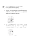
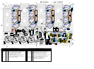

5. Measure the resistor coloured GREEN. The measured value should measure
within + or – 5% value listed in the table below. Replace any resistor that
measured beyond the + or – 5% value listed in the table below.
Resistor Printed Correct
Number Value Measured Value
-5% +5%
R10 4K7 2K25 2K3 2K35
6. Measure across the pair of test points listed in the table below. If the
measured value is not within + or – 10% of the value listed in the table then
replace the resistors shown in the table below.
Test Layout Correct Replace
Points Reference Measured Value Resistors
A to A TP2 to J19 -10% +10% R11, R12, R14
15ohm 17 ohm 19 ohm
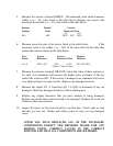
7. Measure the resistors coloured ORANGE. Since the value of these resistors is
0.1 ohm, your ohmmeter will measure the higher series resistance of the test
leads if the resistor is OK. If the resistor is damaged your ohmmeter will read a
very high resistance (an open circuit). Replace any damaged resistors.
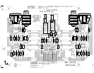
8. Measure the output TO –3 transistors (Q13 to Q28) to determine if any are
damaged. Mark any damaged transistors with a marking pen.
9. Replace any output transistors that you have marked as being damaged.
Replace any diodes that you have found to be damaged. Replace all of the red
transistors that were removed.
10. Inspect the traces on the circuit board for any that have ‘fused’ open or look
like they got very hot. Bridge and solder a piece of wire over any damaged
traces.
AFTER YOU HAVE REPLACED ALL OF THE NECESSARY
COMPONENTS INSPECT THE REPAIRED BOARD FOR ANY
MISSING PARTS, CORRECT VALUES IN THE CORRECT
POSITION AND THAT ALL COMPONENTS ARE SOLDERED.