


6
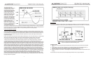
The voltage between the
amplifier?s output and test point
4 is approximately 14.7VDC
derived from the voltage drop
across ZD3 @ ZD4. We call this
voltage the “floating battery”
because it floats on top of the
output audio signal with point 4
always being 14.7VDC greater
than the peak of the output
signal. Point 4 drives the gate of
mos-fet Q11. Q11 controls the
transistors of the upper tier. As
Q11 turns on it's source foward
biases the base of Q13 and Q13
pulls the collector of Q14
towards the 144 volt rail. The
gate to source voltage needed to
turn on Q11 is approximately 3.5
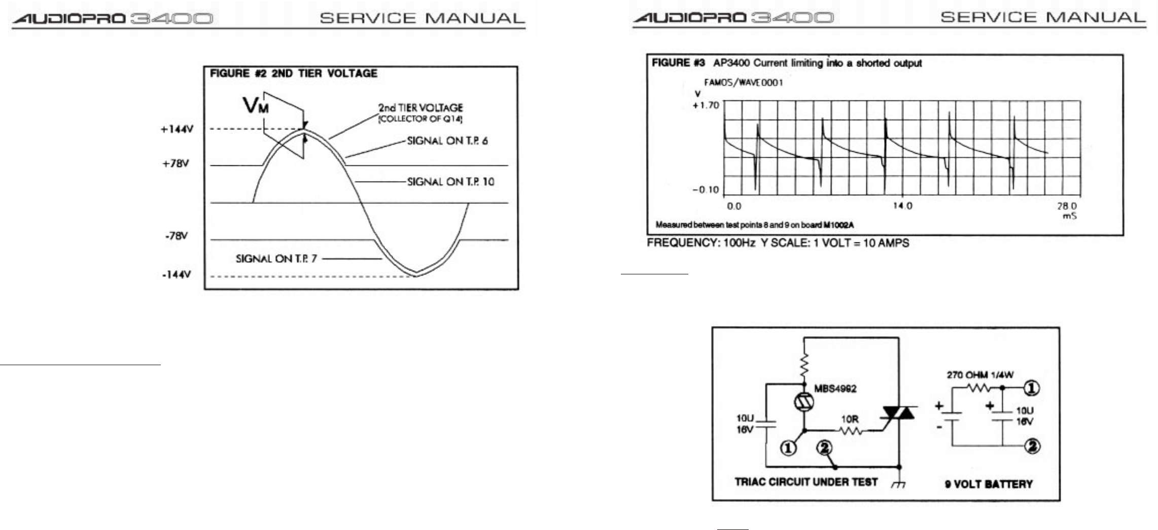
volts. When the peak output
signal is about 67vp (55v-(14.7v-
3.5v)) then Q11 will start to turn on the second tier. The second tier voltage will remain about 11 volts (Vm) above the
peak of the output signal to the point of clipping where this voltage is reduced to about 4 volts. Zener ZD8 protects the
gate source junction of Q11 and also provides a current path through R29 for the “floating battery”.
Current Limit Protection Circuitry
To have an amplifier drive 3000 watts into practically any combination of speaker cabinets and know what is a safe
load and what is not is a very difficult task. An extensive amount of time was spent on the current limit circuitry so that
it may simulate the safe operating area of the output transistors (SOAR curve). No matter how reactive the load may
be the phase shift that it presents, along with it's resistive component is used to set the output current limit of the
output transistor stage.
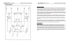
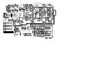
Refer to the schematic of board M1002A while reading the following text. The current limit circuitry is a mirrored image
with circuitry connected to the positive power supply rail being identical (but opposite polarity) to the circuitry
connected to the negative power supply rail. For this reason we will look at the positive side of the circuitry.
Transistor Q9 measures the peak current flowing through resistor R53. The voltage across R53 (as a result of the
current flowing through it) is scaled down by R55, R35, R36, R37, D7 and D11- these parts make up the safe
operating area along with the time constants of C26, R34, C12 and R26. Fig. #3 shows a waveform of the current that
passes through R52 and R53 when the output of the amplifier is shorted to ground. This can only be seen by using an
oscilloscope to measure differentially across R52 and R53. The conditions of the measurement are contained on the
diagram. During current limit when Q9 turns on it reduces the voltage across R42. R42 is in series with a 16 volt zener
(ZD7) and is also in parallel with the junction of Q8. Q8 is normally saturated by the current that flows through R20,
ZD7, R42, and R22. When Q9 reduces the voltage across ZD9 and R42 to below 16.6 volts then Q8 turns off allowing
a charge to build up on C8 through resistors R24 and R25. If current limiting occurs for a long enough duration to
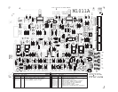
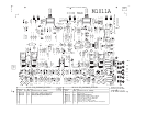
allow C8 to charge to 1.2 volts then Q7 will turn on tripping the relay circuit on board M1011A. As soon as the relay is
turned off the audio signal will be turned off at the voltage amplifiers and will remain off for about 5 seconds before the
relay turns on and allows the audio signal to pass through the amplifier. If a current limit condition is still present then
the whole cycle will occur again and repeat until the load conditions on the amplifier's output are safe for the amplifier.
When a safe load reappears the amplifier will automatically reset and drive that load (the speaker cabinet).
Subwoofers present large inductive loads to the amplifier and are driven at low frequencies where the large current
peaks must be tolerated for short periods of time. To accomodate this type of loading C26 and R34 are used to retard
the firing of Q9 at low frequencies.
7
DC Protection
If a DC voltage greater than 8 volts appears on the output of the amplifier for more than 200 milliseconds then triac
Q30 will turn on holding the output at ground potential. MBS4992 is a device that turns on at either + or - 8 volts DC.
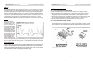
NOTE:
Everytime you replace blown output transistors on a M1002A board
test the DC protection triac with the following circuit.
Conditions of test:
A.
Pass a 100Hz 25v peak signal through the M1002A board under test with no load connected to the amplifier
output.
B.
Connect points 1 and 2 as shown in the diagram. The amplifier should go into protect mode as the triac ( if
working) shorted the output of the amplifier to ground, and the amplifier goes into current limit.
C.
Disconnect the triac test circuit and allow the amplifier to complete it?s protect cycle.
D.
Reverse connections 1 to 2 and 2 to 1 and test again. The same results as in B) should be observed if the triac is
working.
Only test the triac for one protect cycle as prolonged testing will heat the triac to a high temperature.