


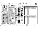

Testing Repaired Circuit Board
Now that you have rebuilt the M1002 or M1002A circuit board. It is just as important to
properly power up the board. If the sinewave doesn’t look right check the signal at test
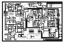
point (1) on
M1002 to ensure that the voltage amplifier on board M1011 or M1011A isn’t
distorting the signal. If there is still a damaged part on the board instantly turning it on
could blow up the board and you would be back where you started.
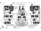
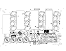
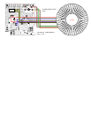
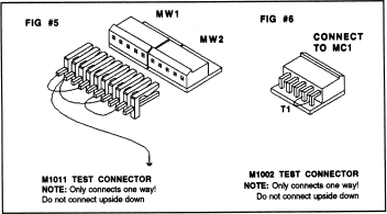
The best method is to connect the test connector shown in figure 3 to the 5 pin molex
connector MC1 and connect the power wires and ground to the power supply.
Connect a digital multimeter to test pins 8 and 9 to measure the bias quiescent current and
place a scope probe on the speaker output. Be sure to turn the quiescent current trimpot
RT1 fully counter clockwise.
Now using a variac slowly turn up the AC main voltage while monitoring the quiescent
voltage and the speaker output trace on the scope. Watching these two test points is a
good indicator of the health of the board. If you have a second multimeter connect it up
from the speaker output to test point 4 or 5. As you variac up also check these DC battery
voltages to ensure that they both increase in voltage to approximately +14 or –14 vdc.
If the board looks OK after variacing up to 120vac then slowly turn up the bias (RT1
trimpot) to obtain 3 to 5 millivolts of bias voltage on test points 8 and 9.
Now power down the board; connect MC1 to circuit board M1011 and variac up the
whole amplifier. Check the speaker output with a 1KHZ sinewave with no load. If this
looks good place the minimum rated load (4 ohm for M1002A, 2 ohm for M1002) on the
speaker output and increase the sinewave amplitude to the point of clipping. If the signal
looks free of oscillation, place a short across the speaker posts. The amplifier should go
into protect mode after 1/10 of a second. Remove the short and the sinewave will appear
6 seconds later.
Reassemble the complete amplifier and run just clipping music or pink noise into the
minimum rated speaker load for that model of amplifier. Let the amplifier heat up for 20
minutes. This will check the thermal mounting of the transistors and for any weak parts
not caught during troubleshooting.
If the amplifier passes this test the product is ready to return to the customer.
Figure 3.
See details of figure 3 in service manual.