


BALANCED, UNBALANCED, AND
FLOATING CIRCUITS
Unbalanced, balanced and floating circuits may all be
transformer isolated. The distinction between them lies
in the way the circuits are referenced to ground (audio
common). A FLOATING circuit has no ground reference,
as illustrated by the Yamaha PM-180, PM-430 and
PM-700 Mixers' Channel Inputs and XLR outputs. A
BALANCED circuit requires either a center tapped
transformer, or resistors from each side of the transfor-
mer to ground; either condition places both sides of the
transformer at equal potential with respect to ground.
In other words, the transformer is balanced with respect
to ground. Electronic balancing, done with "differential"
input or output circuits, can replace transformers, with
similar results. For example, the output of the P-2200
in the "mono" mode is balanced electronically.
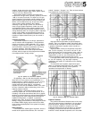
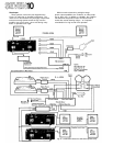
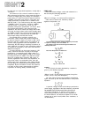
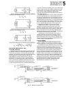
Figure 83 shows transformer created balanced, floating,
and unbalanced lines.
Consider what happens if an RF source (radio station,
CB radio, SCR dimmer, etc.) causes a noise current in
the wires of a balanced circuit. Provided that the source
is physically distant from the circuit (compared to the
distance between the
two
wires),
RF
will
cut
across
both
wires, creating equal noise voltages in both wires. How-
ever, since the signals (wanted voltage) in the two wires
are out of phase with each other, the in-phase noise
(unwanted noise voltage) is effectively canceled.
A balanced line may or may not have a shield. If it
does have a shield, the shield is usually at the same
potential (voltage) as the common or ground wire. Since
the phase cancellation of noise currents in a balanced
line is never perfect in the real world, most low level
balanced circuits (mic or line) are shielded. Twisting the
two internal wires also helps cancel noise.
A floating line is also a two wire circuit, which is
usually created by a transformer. However, unlike a
balanced line, the common or ground voltage has no
direct connection to the circuit. Even so, a floating line
will reject hum and noise as well as a balanced line, and
is often used for audio applications.
TRANSFORMERS
Several applications of audio transformers are dis-
cussed, in specifics, on Pages SIX 4 and SIX 5, the fol-
lowing paragraphs concern general transformer operation.
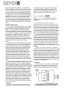
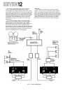
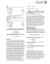
A transformer changes electrical energy at its input
(primary winding) into magnetic energy in its core. This
magnetic energy is transformed back into electrical
energy at the transformer's output (secondary winding).
If the transformer is wound with a greater number of
turns on its primary side than on its secondary side, the
voltage level at the secondary will be lower than on the
primary, and the current level on the secondary will be
higher than on the primary. Since the impedance of a
circuit is equal to the ratio of that circuit's voltage level
divided by its current level, a transformer can transform
impedances as well as voltages and currents. These
actions take place in a precise, mathematical way
described by the equations on the next page:
Fig. 83 - Balanced vs Floating Circuits