


The preparation of complete cables, with connectors
properly installed, is the key to reliable and trouble-free
operation of any sound system. For this reason, the fol-
lowing illustrations are included. Experienced audio
technicians may wish to review these illustrations, even
if they already know how to wire connectors. A few
moments of extra care here can save hours of trouble-
shooting later on.
As a rule, the amount of insulation removed and the
length of exposed cable should be minimized. This
reduces the likelihood of short circuits and improves the
ability of the clamp to grip the cable firmly. Enough
heat should be used to obtain a free flow of solder, but
allow leads to cool quickly after solder flows to avoid
melting insulation. After each connector has been com-
pletely wired, the cable should be tested with an ohm-
meter or a cable tester. Continuity between the various
conductors and their associated connector pins must be
established, and there should
be
infinite
resistance
(an
open
circuit)
between all
connector
pins.
In
most
cases,
especially in portable installations, XLR connectors
should not conduct at all between the shell and pin 1.
This avoids grounding problems from inadvertent touch-
ing of the shell to other devices.
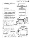
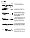
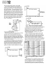
Cables to be connected to terminal strips should be
prepared by stripping the ends and installing crimp-on
or preferably, solder type lugs. If there is any chance
the cable will be strained, use a cable that is constructed
with internal strain relief cord, such as Belden No. 8412.
Crimp a lug onto the cord, and secure the lug to an un-
used terminal. (The cord should be drawn slightly
tighter than the wire leads in order to take the strain
first.)
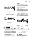
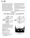
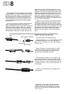
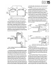
WIRING AN RCA-TYPE PIN PLUG*
Parts identification and cable preparation.
Strip approximately 1/2" of outer insulation. Unwrap
or unbraid the shield and form a lead. Strip approxi-
mately 5/16" of insulation from the center conductor.
Tin both leads.
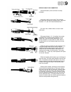
Solder the shield to the outer surface of the shell
connection, allowing enough free shield to wrap the
cable around to the center of the connector. Cool
the connection immediately with pliers.
Insert the center conductor in the hollow pin, and
fill
that
end
with
solder. Cool the connection immedi-
ately
with
pliers.
Clean
any solder
splashes
and
inspect
for burned insulation. Pinch the clamp around the outer
insulation with pliers, firmly, but not so tight as to cut
the insulation.
Slide the shell forward and screw it tightly to the
threaded plug.
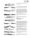
*Switchcraft No. 3502 connector illustrated. Many large
diameter cables are more easily wired to "simple" RCA
type
pin
plugs
without
a
shell
(Switchcraft
No.
3501M,
or
equivalent). The braid can then be soldered directly to the
shell of the plug.