


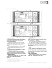
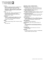
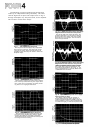
The following are actual oscilloscope photographs
made by an independent testing laboratory. The close
vertical
alignment
of
input
and
output
traces
in
Fig.
21
through
23
depicts
very
low
phase
shift,
so
the
amplifier
will
not
alter
musical
wave
shapes.
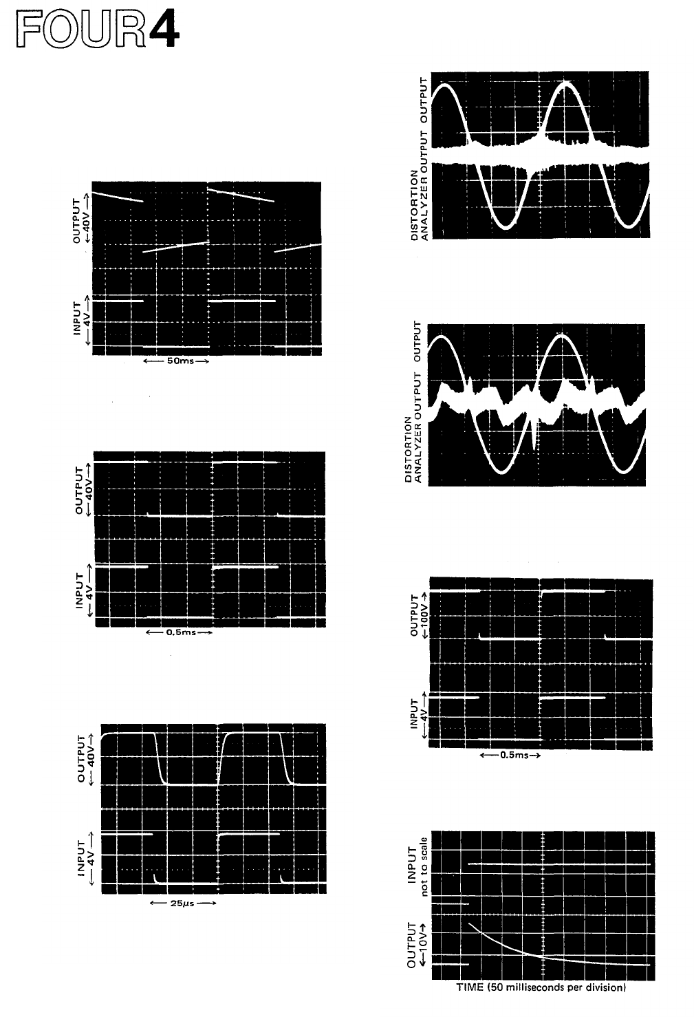
Fig. 21 - 10Hz Square-Wave Response
The output waveform displays very respectable
low frequency
response.
The slight
"
tilt
"
shows
a
DC
gain
of
unity,
which
prevents
damage
to
speakers in the event any DC offset is fed to the
amplifier input.
Fig. 22 - 1,000Hz Square-Wave Response
Near-perfect response is evident in the duplica-
tion
of the
input
waveform
by
the
output
wave-
form. There are no "squiggles" or spikes, mean-
ing there Is no ringing or overshoot.
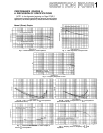
Fig. 23 - 20,000Hz Square-Wave Response
The extremely fast and symmetrical rise and
fall times of the amplifier are evident, demon-
strating the ability to accurately reproduce
musical waveforms and harmonics well beyond
the range of human hearing.
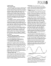
Fig. 24 - 1,000Hz Sine Wave, shown with Highly-
Magnified Noise and Distortion Components
Even
at
full
230 watt
output
(8-ohms), the
P-2200's distortion is so low that it is almost
burried in the noise, which is at least 110dB
below the
sine
wave
output.
The
sine
wave
is
clean and symmetrical.
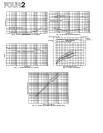
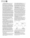
Fig.
25-20,000Hz
Sine
Wave,
shown
with
Highly-
Magnified Noise and Distortion Components
While no amplifier should ever have to pro-
duce 230 watts continuous output at 20kHz,
the
P-2200
does
it
with
low
distortion,
and
symmetrical reproduction. As In Fig. 11, the
noise (magnified here) is actually better than
110dB below the sine wave.
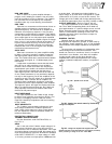
Fig. 26 - Square-Wave Response into a Highly-
Inductive Load (at 1kHz)
The ability of the P-2200 to maintain a
sharply defined square wave output into a
reactive load demonstrates stability under the
worst conditions. There is still a complete lack
of unwanted ringing, as well as low phase shift.
Fig. 27 - Unit-step Function Response