


EQUALIZATION, HIGH AND LOW PASS FILTERS
Equalization, originally, was the process of
"equalizing" the levels of the various audio frequency
bands
for
a
"flat"
system
response.
The
term
now
encompasses many different devices and techniques
that are used for effects purposes as well as to "smooth"
the response of a system.
Room Equalization
A room, whether it be a recording studio, concert hall,
airport lounge, or night club, has a frequency response of
its own. Carpeting, draperies, and padded furniture can
soak up sound, primarily at high frequencies. The high
reverberation time of large concert halls usually affects
the low frequency sounds more than the high frequency
sounds. For these, and other reasons, it may be desirable
to shape the frequency response of a sound system to
compensate for the response of the room.
Generally, acoustic solutions are the best answers to
these acoustic problems, especially for severe resonances
or excessive peaks or dips in the room response. However,
for final smoothing of system response, or for portable
systems where acoustic solutions may be impractical,
electronic room equalization can be a valuable aid.
There are several different methods of room equali-
zation. Most methods use a specified sound source, such
as pink or white noise, or a tone burst which is played
through the system. The sound is monitored at some
point (or at several points) in the room using a real time
monitoring device (real time means that the monitor
displays the system response on an instantaneous basis).
A graphic equalizer, or other type of equalizer is used to
adjust the system response to compensate for response
irregularities displayed on the real time monitor.
Equalization can also help to smooth the response of
a speaker system, a microphone, or most any type of
audio device. However, this can cause problems, as
explained below. These frequency response shaping
techniques can also be used for special effects: to
increase the sizzle of a cymbal crash, to sweeten the
sound of a violin or to add warmth to a singer's voice.
Equalizers come in all types and varieties. Some are
most suitable for a specific task, others have more
general uses.
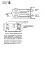
Graphic Equalizers
A "graphic" equalizer is a multi-frequency, band
reject filter or a bandpass/reject filter. Unlike the input
channel equalizers on a mixer, a graphic equalizer can
simultaneously operate at several 1-octave, 1/2-octave, or
1/3-octave frequency bands. Most graphic equalizers use
l.S.O. standardized center frequencies. (I.S.O. is an
acronym for the International Standards Organization.)
The units are called "graphic" because most have linear
slide controls, and when they are set they create a visual
image that resembles the overall frequency response
curve
of
the
unit.
Some
so-called graphic equalizers
use
rotary controls. A graphic equalizer may provide attenua-
tion only (band reject), or attenuation and boost (band
pass/band reject).
Usually, each speaker feed requires its own channel of
professional-type graphic equalization which is installed
between the mixer output and the power amplifier input.
Stage monitor feeds, for example, may require very
different equalization than house feeds. In recording and
broadcast applications, the graphic equalization applied
to the recording is usually for tonal considerations, and
to avoid exceeding the frequency response limits of the
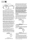
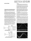
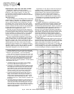
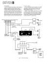
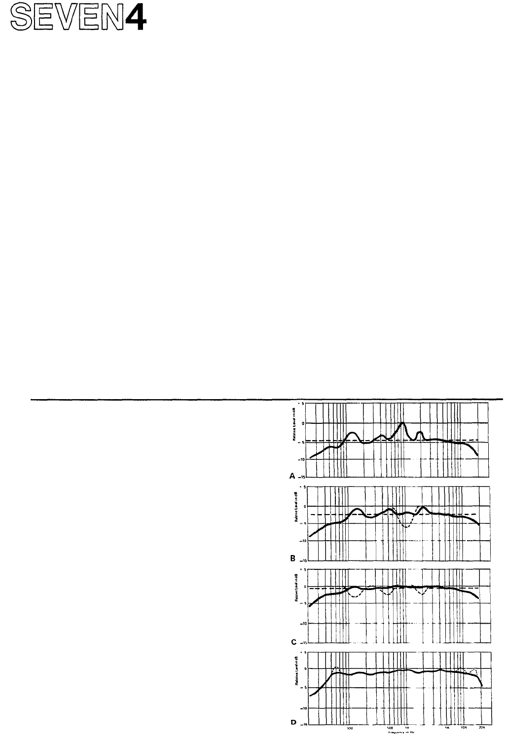
Graphic Equalization can be used to reduce resonant peaks
in the overall sound system (which consists of the microphones,
instruments, room and speakers. 1-octave EQ illustrated.)
NOTE: Shaded area represents sound level above which feed-
back will occur. If any frequency is reproduced at a level in the
shaded zone. then either the overall sound level must be turned
down (lower volume), or the graphic equalizer must be used to
reduce the level of the frequency band where the excess level
occurs. Proper selection and placement of microphones and
speakers can reduce the need for equalization. "He who equalizes
least equalizes best" (anon.).
A. A microphone picks up a vocal peak at 1kHz, making it
necessary to reduce the average level (horizontal dotted
line) to some 5dB below the feedback point.
B. Lowering the 1 kHz Graphic EQ slider about 5dB pulls down
the resonant peak and allows the overall volume to be raised
several dB. Any further increase of the volume control may
cause feedback to occur at several frequencies where lesser
peaks occur: an electric bass at 125Hz an acoustic guitar
resonance at 500Hz, and a stage monitor speaker peak at
2kHz that is being picked up by a nearby microphone.
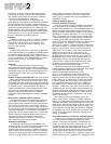
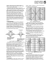
C. To allow the average level to be raised further, the 125Hz,
500Hz, and 2kHz Graphic EQ sliders are pulled down
slightly. This smooths the overall frequency response and
allows maximum loudness throughout the audio spectrum.
A
natural
roll-off
at
the
low
and
high
ends
remains,
and
is
preferred by many users. If flatter response is required, it can
be achieved.
D. If the input channel tone controls were used to bring up the
high and low ends of the spectrum, too much lift would
occur toward the middle, causing feedback. Also. too much
overall
bass
boost
would
waste
amplifier
power
and
might
lead
to
burned
out
speakers
or
excess
distortion.
By
lifting
the 62.5Hz, 8kHz and 16kHz Graphic EQ sliders slightly, the
response is flattened without unwanted distortion, and
without creating feedback.
Fig. 67 - How to Use 1-Octave Graphic Equalization