


81
SET MENU
ADVANCED
OPERATION
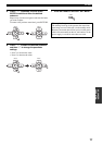
■ Dynamic range F)D. RANGE
Use this feature to select the amount of dynamic range
compression to be applied to your speakers or
headphones. This setting is effective only when this unit is
decoding Dolby Digital and DTS signals.
Speaker SP D.R
Adjusts the speaker compression.
Headphone HP D.R
Adjusts the headphone compression.
Choices: MIN, STD, MAX
• Select “MIN” (minimum) if you regularly listen at low
volume levels.
• Select “STD” (standard) for general use.
• Select “MAX” (maximum) to preserve the greatest
amount of dynamic range.
■ Audio settings G)AUDIO SET
Use this feature to adjust the overall audio settings of this
unit.
Muting type MUTE TYP.
Use this feature to adjust how much the mute function
reduces the output volume (see page 32).
Choices: FULL, –20dB
• Select “FULL” to completely mute all the audio
output.
• Select “–20dB” to reduce the current volume by 20 dB.
Audio delay A.DELAY
Use this feature to delay the sound output and synchronize
it with the video image. This may be necessary when
using certain LCD monitors or projectors.
Control range: 0 to 160 ms
Control step: 1 ms
Tone bypass TC.BYPASS
Use this feature to select whether audio output bypasses
tone control circuitry when “TREBLE” and “BASS” are
set to 0 dB (see page 31).
Choices: AUTO, OFF
• Select “AUTO” if you want signals to bypass tone
control circuitry to provide the purest signal possible.
• Select “OFF” if you do not want signals to bypass tone
control circuitry.
Use this menu to reassign the input jacks, select the input
mode or rename the input source.
■ Input assignment
A)INPUT ASSIGN
Use this feature to assign the input jacks according to the
component to be used if the initial settings of this unit do
not correspond to your needs. Change the following
parameters to reassign the respective jacks and effectively
connect more components.
Once the input jacks are reassigned, you can select the
corresponding component by using the INPUT selector on
the front panel (or the input selector buttons on the remote
control).
For COMPONENT VIDEO jacks A, B and C
C.V[A]
C.V[B]
C.V[C]
Choices: [A] DVD, DTV/CBL, V-AUX, DVR
[B] DVD, DTV/CBL, V-AUX, DVR
[C] DVD, DTV/CBL, V-AUX, DVR
For OPTICAL INPUT jacks 1and 2
IN (1)
IN (2)
Choices: (1) CD, MD/CDR, DVD, DTV/CBL, V-AUX,
DVR
(2) CD, MD/CD-R, DVD, DTV/CBL, V-AUX,
DVR
For COAXIAL INPUT jack 3 COAXIAL IN (3)
Choices: (3) CD, MD/CD-R, DVD, DTV/CBL, V-AUX,
DVR
• You cannot select a specific item more than once for the same
type of jack.
• When you connect a component to both the DIGITAL INPUT
(COAXIAL) and DIGITAL INPUT (OPTICAL) jacks, priority
is given to the signals input at the DIGITAL INPUT
(COAXIAL) jack.
2 INPUT MENU
Notes