14
Connecting Video Components
■ Audio signal jacks
Be sure to connect the right channel (R), left channel (L), input (IN) and output (OUT) properly.
■ Video signal jacks
Be sure to connect the input (IN) and output (OUT) properly.
■ TV monitor with a 21-pin connector
Make a connection as shown on page 15 with a commercially available SCART-plug connector cable.
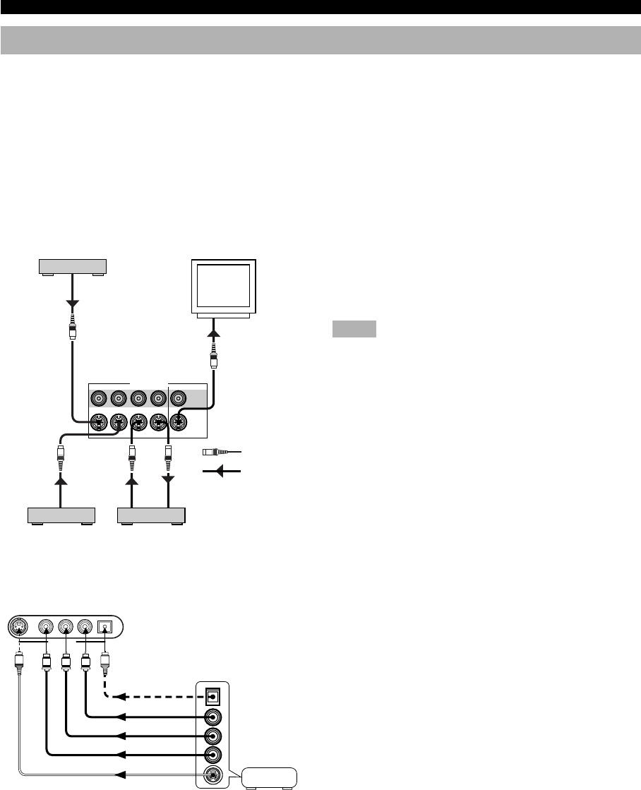
■ S VIDEO jacks
If your video component has “S” (high-resolution) video
jacks, they can be connected to this unit’s S VIDEO jacks.
Otherwise, connect the composite video jacks of your video
component to this unit’s composite video jacks.
Notes
• Use a special S VIDEO cable (commercially available) for the S
VIDEO connection.
• If video signals are input from both the S VIDEO input and
composite input jacks, the signals will be directed to their
respective output jacks.
AUDIO OUT R
AUDIO OUT L
VIDEO OUT
OPTICAL OUT
S VIDEO OUT
O
V
L
R
S
VIDEO AUX
S VIDEO VIDEO L AUDIO R OPTICAL
S VIDEO
VIDEO
MONITOR OUT
DVD D-TV/CBL
IN
VCR 1
OUT
VIDEO SIGNAL
S VIDEO OUT
S VIDEO
OUT
S VIDEO IN
S VIDEO IN
S
S
S
S
S
S VIDEO OUT
S
DVD player
Video monitor
S Video signal
Signal flow
TV/digital TV,
cable TV or
satellite tuner
VCR
Game console
CONNECTIONS
■ VIDEO AUX jacks (on the front panel)
These jacks are used to connect any video input source such
as a game console to this unit.
0103V520RDS10-20_EN 2/1/1, 2:23 PM14


