


9
English
BASIC OPERATION
ADVANCED OPERA
TION
APPENDIX
INTRODUCTION
PREPARATION
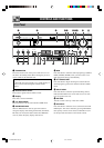
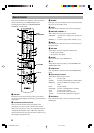
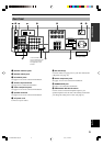
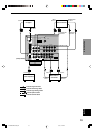
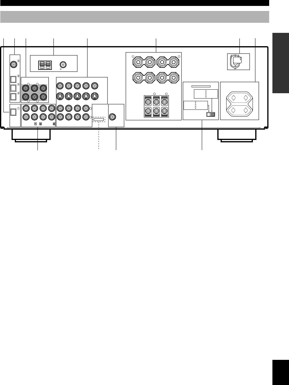
Rear Panel
1 DIGITAL OUTPUT jacks
2 DIGITAL INPUT jacks
3 6CH INPUT jacks
See pages 12 and 13 for connection information.
4 Antenna input terminals
See page 26 for connection information.
5 Video component jacks
See pages 14 and 15 for connection information.
6 Speaker terminals
See pages 16 and 17 for connection information.
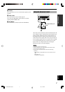
7 AC power cord
Connect to a power outlet.
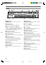
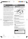
CONTROLS AND FUNCTIONS
As this terminal is used
for an examination in the
factory, do not connect
any equipment to this
terminal.
1
2
3 4
5
6
7
8
0 q
9
SWITCHED
100W MAX. TOTAL
AC OUTLETS
IMPEDANCE SELECTOR
SET BEFORE POWER ON
MAIN A OR B: 4
MIN. /SPEAKER
A
+
B: 8
MIN. /SPEAKER
CENTER
: 6
MIN. /SPEAKER
REAR
: 6
MIN. /SPEAKER
SPEAKERS
MAIN
+ –
R L
A
– +
B
CENTER REAR
(SURROUND)
R
L
+
–
S VIDEO
VIDEO
MONITOR OUT
DVD
DVD
DVD
D-TV/CBL
D-TV/CBL
D-TV/CBL
IN
VCR 1
OUT
VIDEO SIGNAL
AUDIO SIGNAL
SUB
WOOFER
OUTPUT
IN
VCR 1
OUT
OUT(REC)
IN(PLAY)
CD
AUX
MD/CD-R
MD/CD-R
MD/CD-R
R
L
DIGITAL
OUTPUT
OPTICAL
OPTICAL
COAXIAL
AM ANT GND
FM ANT
75
UNBAL.
TUNER
MAIN
CENTER
SUB WOOFER
SURROUND
DIGITAL
INPUT
6CH INPUT
CD
MAIN A OR B: 8
MIN. /SPEAKER
A
+
B:
16
MIN. /SPEAKER
CENTER
: 8
MIN. /SPEAKER
REAR
: 8
MIN. /SPEAKER
R
L
R
L
MAINS
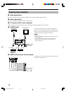
8 AC OUTLET(S)
Use these outlets to supply power to your other audio/video
components (see page 18).
9 Audio component jacks
See pages 12 and 13 for connection information.
0 SUBWOOFER jack
See page 17 for connection information.
q IMPEDANCE SELECTOR switch
Use this switch to match the amplifier output to your
speaker impedance. Set this unit in the standby mode before
you change the setting of this switch (see page 18).
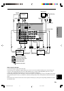
(Europe model)
0102V520RDS01-09_EN 1/31/1, 4:21 PM9