FUNCTIONAL OVERVIEW
7
INTRODUCTION
1
English
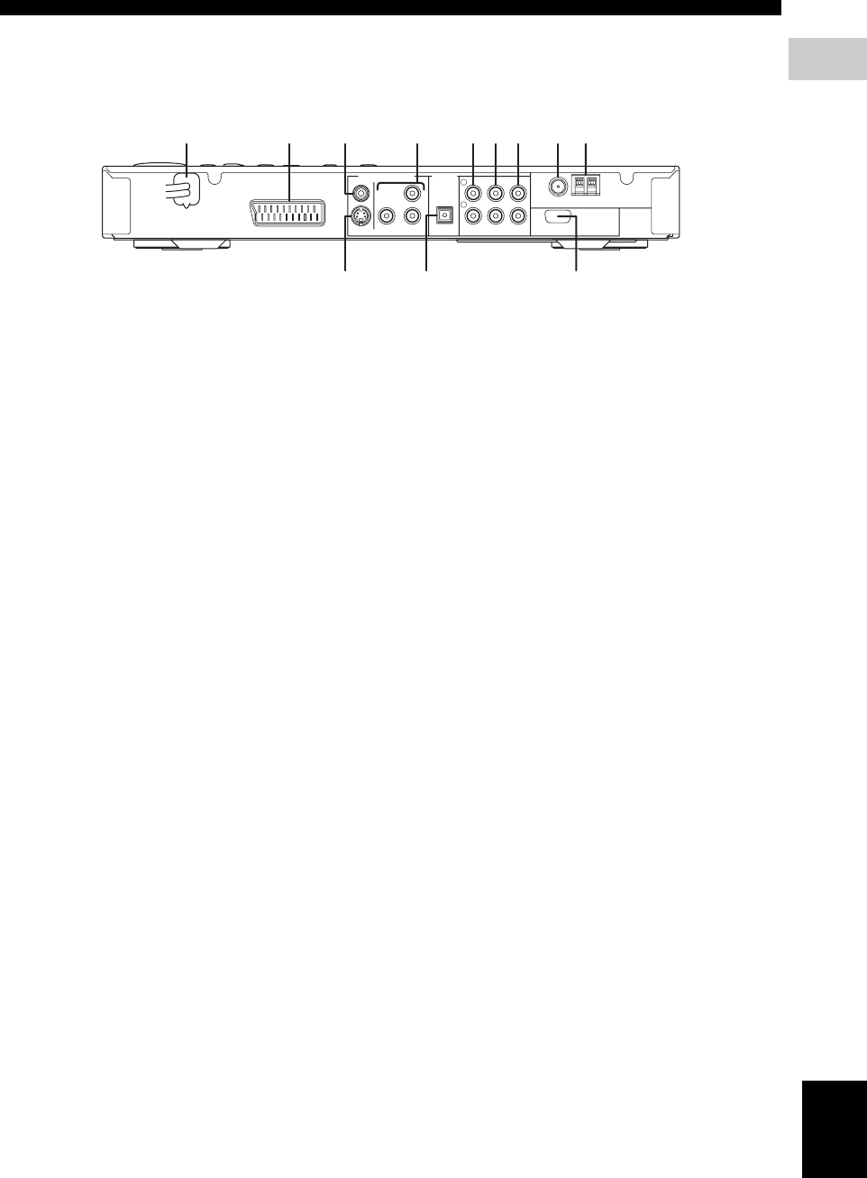
■ Rear panel (DVR-S300)
(U.K. and Europe models)
1 AC power cord
Connect to a standard AC outlet.
2 AV MONITOR OUT terminal
(U.K. and Europe models only)
Connect to your TV (see page 19).
3 VIDEO output terminal
Connect to the video (composite) jack on your TV
(see page 19).
4 COMPONENT VIDEO OUT terminal
Connect the the Y P
B/CB PR/CR jacks on your TV (see
page 19).
5 LINE OUT terminal
Connect to the AUDIO IN jacks on your VCR.
6 TV IN terminal
Connect to the corresponding AUDIO OUT jacks on
your TV (see page 19).
7 AUX IN terminal
Connect to the AUDIO OUT jacks on your VCR or
cassette deck.
8 FM ANT terminal
Connect the FM antenna.
9 GND and AM ANT terminals
Connect the AM loop antenna.
0 S VIDEO output terminal
Connect to the S-video jack on your TV or VCR.
A OPTICAL DIGITAL IN terminal
Connect to the DIGITAL OUT jack on your digital
audio component.
B SYSTEM CONNECTOR terminal
Connect the subwoofer.
SYSTEM
CONNECTOR
AUX INTV INLINE OUT
S VIDEO
AV MONITOR OUT
(DVD ONLY)
VIDEO
OPTICAL
COMPONENT
Y
P
R PB
PCM/DTS
q
DIGITAL
DIGITAL INVIDEO OUT (DVD ONLY)
FM
ANT
AM
ANT
GND
TO SUBWOOFER
75Ω UNBAL
L
R
9821 4 5 6 73
B0A


