


CONNECTIONS
15
PREPARATION
English
Do not connect this unit or other components to the mains
power until all connections between components are
complete.
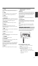
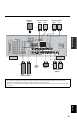
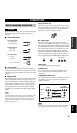
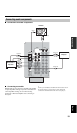
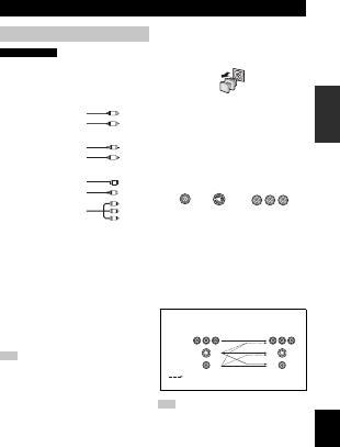
■ Cable indications
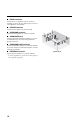
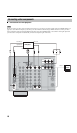
■ Analog jacks
You can input analog signals from audio components by
connecting audio pin cable to the analog jacks on this unit.
Connect red plugs to the right jacks and white plugs to the
left jacks.
■ Digital jacks
This unit has digital jacks for direct transmission of digital
signals through either coaxial or fiber optic cables. You
can use the digital jacks to input PCM, Dolby Digital and
DTS bitstreams. When you connect components to both
the COAXIAL and OPTICAL jacks, priority is given to
the input signals from the COAXIAL jack. All digital
input jacks are compatible with 96-kHz sampling digital
signals.
This unit handles digital and analog signals independently. Thus
audio signals input to the analog jacks are only output to the
analog OUT (REC) jacks. Likewise audio signals input to the
digital (OPTICAL or COAXIAL) jacks are only output to the
DIGITAL OUTPUT jack.
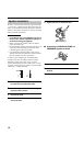
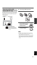
Dust protection cap
Pull out the cap from the optical jack before you connect
the fiber optic cable. Do not discard the cap. When you are
not using the optical jack, be sure to put the cap back in
place. This cap protects the jack from dust.
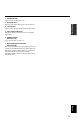
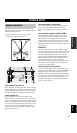
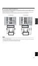
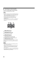
■ Video jacks
This unit has three types of video jacks. Connection
depends on the availability of input jacks on your monitor.
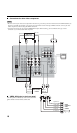
The signals input through the S VIDEO jacks on this unit
are automatically converted for output through the VIDEO
jacks. When VIDEO CONV. is set to ON (see page 64),
signals input through the VIDEO jacks can be output
through the S VIDEO and COMPONENT VIDEO jacks.
Likewise, signals input through the S VIDEO jacks can
also be output through the COMPONENT VIDEO jacks.
VIDEO jacks
For conventional composite video signals.
S VIDEO jacks
For S-video signals, separated into luminance (Y) and
color (C) video signals to achieve high-quality color
reproduction.
COMPONENT VIDEO jacks
For component signals, separated into luminance (Y) and
color difference (P
B, PR) to provide the best quality in
picture reproduction.
When signals are input through both the S VIDEO and VIDEO
jacks, signals input through the S VIDEO jack have priority.
CONNECTIONS
Before connecting components
Note
CAUTION
S
V
O
V
V
V
L
R
C
Y
P
B
PR
left analog cables
right analog cables
optical cables
coaxial cables
video cables
S-video cables
For analog signals
For digital signals
For video signals
component video cables
Note
VIDEO
S VIDEO
COMPONENT VIDEO
P
R
P
B
Y
S VIDEO
VIDEO
COMPONENT
VIDEO
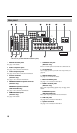
Signal flow inside this unit
Only when VIDEO CONV. is set to ON
(see page 64).
Output
(MONITOR OUT)
Input