


Chapter 2 - Installing the Yamaha CDR400At Drive
10
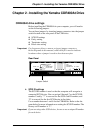
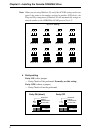
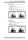
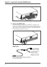
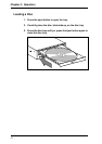
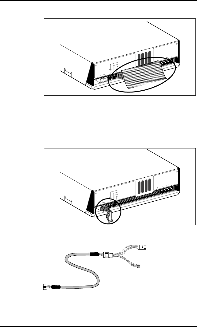
8. Connect the AUDIO cable.
Connect the single 4-pin connector (Sound Blaster compatible) to the
sound card. Connect the 4-pin connector at the other end of the cable (the
larger connector) to the AUDIO OUT connector on the CDR400At drive.
The polarizing lug should be at the top.
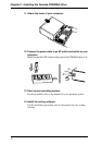
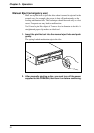
AUDIO cable
R G L
1 2 4
ID SELECT
PARITY
TERMINATOR
BLOCK SIZE
AUDIO OUT
VZ49880-0
1 +5V G +12V
VZ49880-0
SCSI
INTERFACE
CONNECTOR DC INPUT
R G L
1 2 4
ID SELECT
PARITY
TERMINATOR
BLOCK SIZE
AUDIO OUT
VZ49880-0
1 +5V G +12V
VZ49880-0
SCSI
INTERFACE
CONNECTOR DC INPUT
To the CDR400At
4-pin connector (large)
To the CDR100/102
(3-pin connector)
To the Sound Card (Sond Blaster compatible)
4-pin connector (small)
* Simultaneous use with the
CDR400At is not possible.